Soil dowels
Table of contents
1. Slope stability, general stability
The slipping of a moving body along a failure line in which the soil’s shear strength is exceeded, is called slope failure. For a retaining structure (e.g. retaining walls, cantilever walls, gabion walls etc.) as a part of the moving body the slippage along a failure line together with the surrounding ground has to be examined to provide the general safety. In the ultimate limit state the soil’s shear strength along the failure line is also exceeded here.
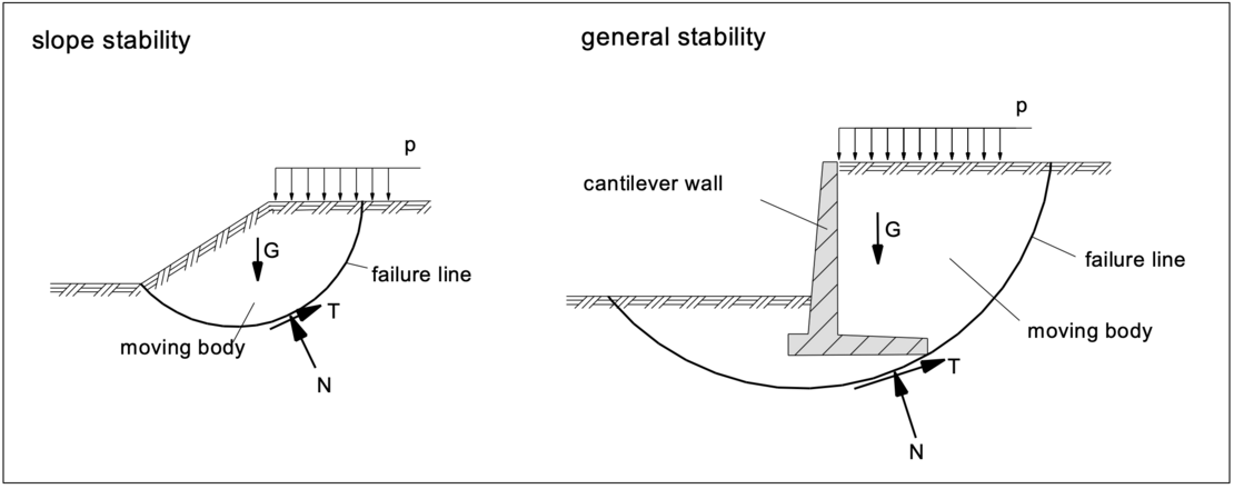
The failure mechanisms to be investigated and the verification methods to be applied are described in DIN 4084, to which DIN EN 1997 refers to in the section "Overall stability". These verifications are carried out in accordance with DIN EN 1997 for the GEO-3 limit state (design approach 3).
For convenient verifications, simple geometries are selected for the moving (sliding) bodies. Preferably, a circle is assumed. The position of the center of the sliding circle is varied in order to determine the radius and position of the most unfavorable circle. In the ultimate limit state, the moving body is assumed to be rigid, with relative movements occurring only along the sliding surface.
Generally, the most unfavorable slip surface runs through the base of the slope in the case of a slope failure with homogeneous soil with an internal friction angle of φ’>5°, and for retaining structures through the earth-side base of the foundation, see the above figures.
2. Calculation method
According to DIN 4084, the following methods are available for the calculation of the slope stability or the overall stability:
- slice method: circular and non-circular slip surfaces
- sliceless method for circular slip lines
- methods with polygonal slip surfaces
- vertical slice method
- wedge mechanisms with intermediate slip surfaces
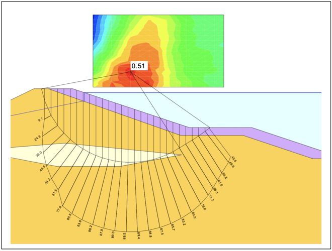
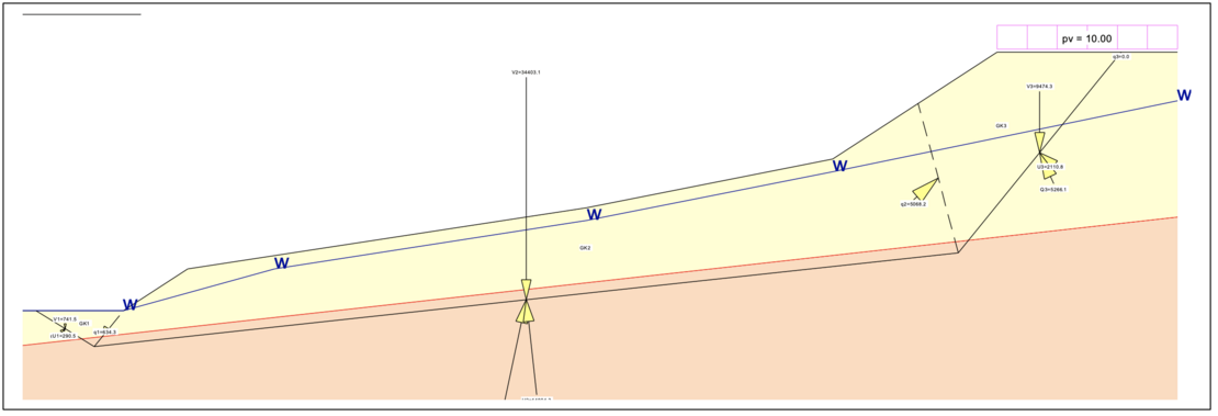
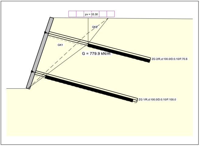
In most cases it is sufficient to select circles as possible slip surfaces. In the case of the overall stability with retaining structures, joints or straight fault zones or soil layers with a low shear strength and in the case of slopes with structural elements, straight slip lines and combined fracture mechanisms are suitable, see the examples shown below, calculated with GGU-STABILITY.
Slice method with circular slip surface:
Wedge mechanisms with intermediate slip surfaces:
Vertical slice method, here with tension elements:
For all systems, the position of the most unfavorable slip surface must be determined and is not known prior to computations. The calculation of the stability at several slip surfaces thus provides the lowest safety.
With regard to the fracture mechanisms and calculation methods that can be used to determine the stability of slopes and the overall stability, DIN EN 1997 refers to DIN 4084.
For further information to calculation methods and influencing variables please see the glossary entry „Slope stability, overall stability“.
3. Soil dowels
Soil dowels are capable of transmitting shear forces at the level of the slip surface and transferring them to the soil below the slip surface.
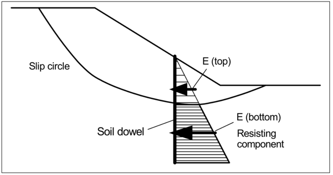
For this purpose, the values of the earth pressures to be transmitted by the soil dowels must be determined. In addition, the design force that can be taken up by the soil dowel must be known.
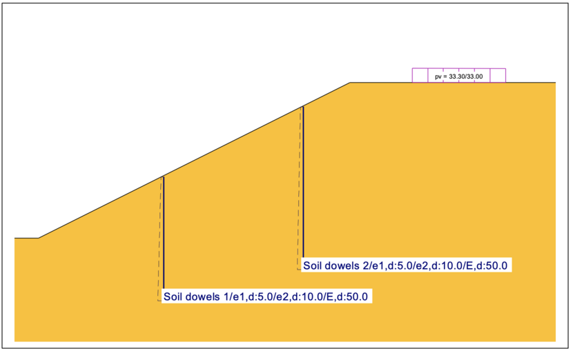
When investigating slip circles, the relevant earth pressure force component (which lies outside of the moving body) for soil dowels is determined and applied to the lever arm of the intersection point of the soil dowel with the slip circle. The computer program GGU-STABILITY computes the relevant slip mechanism taking into account the resulting earth pressure force on the soil dowel, cf. the following printout of results of a slope stability analysis:
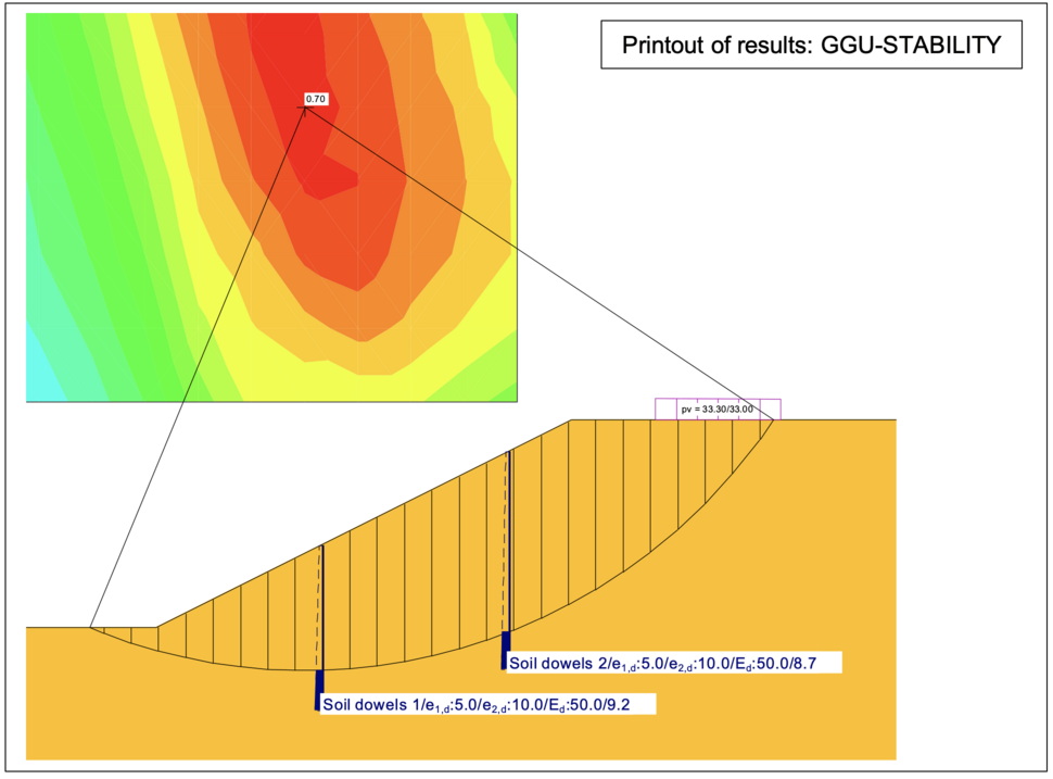
The effect of soil dowels will only be considered when they intersect the slip surfaces!
Notes on use
All texts, images and media listed here are subject to copyright and are the intellectual property of Civilserve GmbH. Use is only permitted with appropriate reference and a link to this source.