Slope stability, overall stability
Table of contents
1. Slope stability, general stability
The slipping of a moving body along a failure line in which the soil’s shear strength is exceeded, is called slope failure. For a retaining structure (e.g. retaining walls, cantilever walls, gabion walls etc.) as a part of the moving body the slippage along a failure line together with the surrounding ground has to be examined to provide the general safety. In the ultimate limit state the soil’s shear strength along the failure line is also exceeded here.
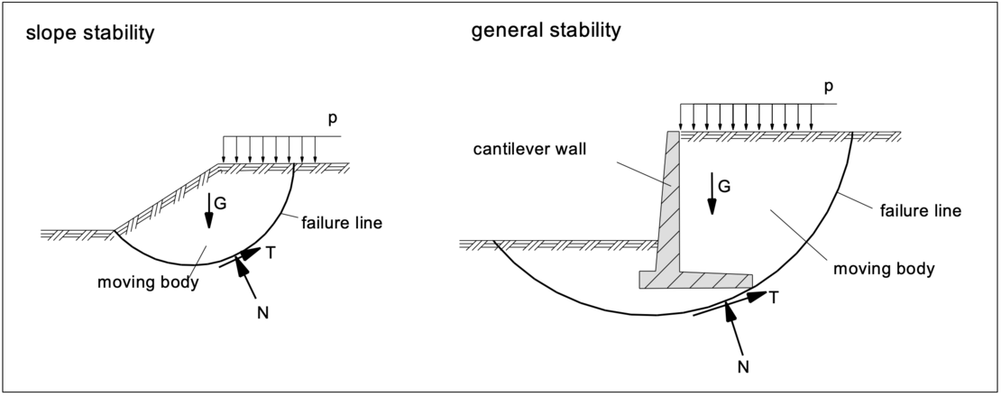
The failure mechanisms to be investigated and the verification methods to be applied are described in DIN 4084, to which DIN EN 1997 refers to in the section "Overall stability". These verifications are carried out in accordance with DIN EN 1997 for the GEO-3 limit state (design approach 3).
For convenient verifications, simple geometries are selected for the moving (sliding) bodies. Preferably, a circle is assumed. The position of the center of the sliding circle is varied in order to determine the radius and position of the most unfavorable circle. In the ultimate limit state, the moving body is assumed to be rigid, with relative movements occurring only along the sliding surface.
Generally, the most unfavorable slip surface runs through the base of the slope in the case of a slope failure with homogeneous soil with an internal friction angle of φ’>5°, and for retaining structures through the earth-side base of the foundation, see the above figures.
2. Calculation method
According to DIN 4084, the following methods are available for the calculation of the slope stability or the overall stability:
- slice method: circular and non-circular slip surfaces
- sliceless method for circular slip lines
- methods with polygonal slip surfaces
- vertical slice method
- wedge mechanisms with intermediate slip surfaces
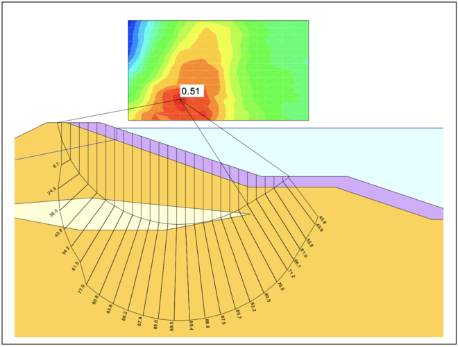
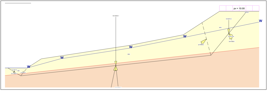
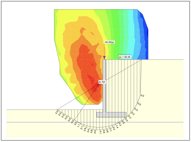
In most cases it is sufficient to select circles as possible slip surfaces. In the case of the overall stability with retaining structures, joints or straight fault zones or soil layers with a low shear strength and in the case of slopes with structural elements, straight slip lines and combined fracture mechanisms are suitable, see the examples shown below, calculated with GGU-STABILITY.
Slice method with circular slip surface:
Wedge mechanisms with intermediate slip surfaces:
Slice method with a circular slip surface through the earth-side base of the foundation:
Vertical slice method, here with tension elements:
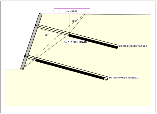
For all systems, the position of the most unfavorable slip surface must be determined and is not known prior to computations. The calculation of the stability at several slip surfaces thus provides the lowest safety.
With regard to the fracture mechanisms and calculation methods that can be used to determine the stability of slopes and the overall stability, DIN EN 1997 refers to DIN 4084.
3. Consideration of groundwater
Approach of flow pressure by hydrostatic water pressure difference
For simplification, the water pressure can be assumed as a hydrostatic force acting in horizontal direction up to the lower edge of the (here: circular) sliding surface. When the water level in front of the embankment is lower than the groundwater level, the water flows down its gradient and exerts a flow pressure on the embankment’s grain structure. A simple, but on the safe side, estimation is to assume the hydrostatic excess water pressure as an external horizontal force Wk.
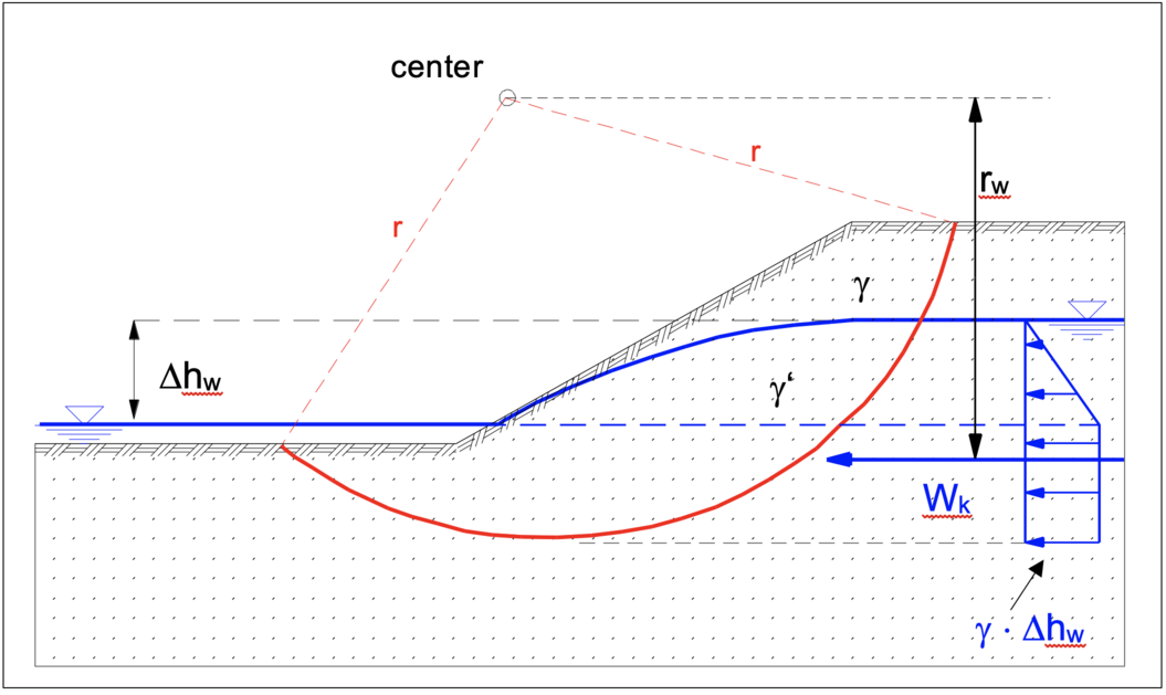
For the computation of effects and resistances to be compared in the course of the verification of the slope stability, the unit weight under buoyancy of the saturated soil is applied for the moving body below the seepage line and above the slip surface.
Approach of water pressure from potential flow
In contrast to the previous verification method, this method includes the pore water pressure in the calculation which must be known along the assumed (here: circular) sliding surface. Therefore, prior to the verification of the slope stability, a hydraulic computation must be performed to determine the flow net.
For the computation of effects and resistances to be compared in the course of the verification of the slope stability, the unit weight of the saturated soil and the pore water pressure along the slip surface is applied for the moving body below the seepage line and above the slip surface.
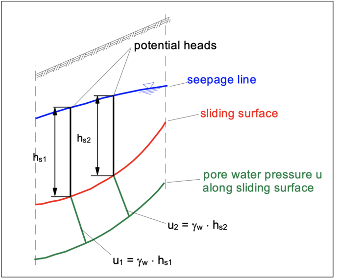
If no flow net is available, the pore water pressure “u” can be determined approximately at any point of the sliding surface with sufficient accuracy, in which for calculation with

for hS the vertical distance above the considered point to the seepage line is applied.
4. Governing equations for circular slip surfaces
To determine the slope stability, moments of resistance are related to moments of actions, both around the center of rotation. Moments of actions are formed from self-weight, water excess pressure and live loads. Moments of resistance result from shear forces along the circular slip surface. The shear forces in the slip surface depend on the normal force on the slices’ slip surface.
4.1 Approach of flow pressure by hydrostatic water pressure difference
The equation to be solved iteratively to determine the degree of utilization μ for the subdivision of the moving body into “i” slices is:

The additional moment ∑Ms,d from the characteristic water excess pressure resultant Wk with the lever arm rw is included in the moments of actions:

In case of a water-saturated slice the weight G'i of the slice under buoyancy has to be applied.
The design value of the shear parameters is calculated as follows:

Pvi,d represents the design value of an external vertical action P on the slice i of width bi. ϑ describes the angle between the straight connection of the center of the sliding circle and the center of the bottom of the slice and the vertical.
4.2 Approach of water pressure from potential flow
The most accurate results are obtained with prior calculation of the flow net and an approach of the potential heads along the slip surface. Especially in case of strongly curved flow lines and steep water surface plane, the increase of effective stresses is taken into account, so that the slope safety is calculated "more accurately". The equation to be solved iteratively to determine the degree of utilization μ for the subdivision of the moving body into “i” slices is:

The additional moment ΣMw,d results from horizontal and vertical water pressure acting on the slope.
The total pore water pressure u is composed of two parts, the pore water pressure u0i and the excess pore water pressure Δui due to a possible consolidation of the soil in the slice i.

In case of a water-saturated slice, the (total) weight Gi is calculated with:

5. Variables influencing the stability
Soils:
- The stability of slopes depends on the stratification of the soils. Geological interference zones, zones of weak shear strength and fill materials reduce the stability.
The presence of water has a significant influence on stability:
- Excess pore water pressure reduces effective stresses and thus reduces the maximum shear force at failure. The safety is reduced.
- Groundwater: groundwater in the embankment creates a flow towards the toe of the embankment. As a result of a water leakage on the slope erosion (soil washout) can occur which reduces stability.
- Surface water: Precipitation and other inflows of water can lead to erosion (soil washout), which reduces stability.
- Water in lakes and rivers: Wave action can erode the slope, reducing stability. In the case of rapid water level drops, the resulting excess pore water pressures must be taken into account.
Variable actions (live loads):
- Variable actions in the immediate slope area reduce stability.
6. Verification of the overall stability
The overall stability of retaining structures has the same soil mechanical failure mechanisms as the slope stability. Therefore, the calculation procedures do not differ from those derived for the slope failure.
Within the moving body the retaining wall’s dead weight has to be taken into account which has no influence on the basic failure mechanics though.
The computer programs
- GGU-CANTILEVER (cantilever walls)
- GGU-UNDERPIN (underpinning)
- GGU-GABION (supporting structures using concrete elements, block layers and gabions)
- GGU-RETAIN (design of sheet pile walls, soldier pile walls, cast-in-place concrete walls, bored pile walls, MIP walls and combined sheet pile walls)
provide further verifications for retaining structures. These programs provide a very convenient interface to the computer program GGU-STABILITY for the analysis of the slope stability and the overall stability.
7. Calculation example, video: Verification of safety against slope failure
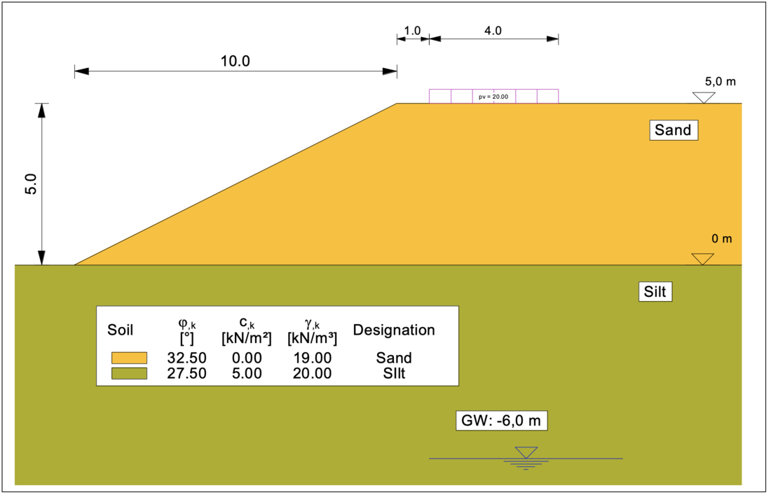
For the example of an embankment shown below and loaded at the top of the embankment with a live load of p = 20 kN/m², the following video demonstrates how the computer program GGU-STABILITY can be used to verify the slope safety for the design situation DS-P.
The extremely practical and user-friendly "Common systems" menu is used to generate the system.
Notes on use
All texts, images and media listed here are subject to copyright and are the intellectual property of Civilserve GmbH. Use is only permitted with appropriate reference and a link to this source.