Shear strength
Table of contents
1. Shear strength
The grain-to-grain skeleton of a soil carries the applied loads. Knowledge of the load-bearing capacity of this grain structure is therefore of decisive importance when verifying the stability of foundations, slopes etc.
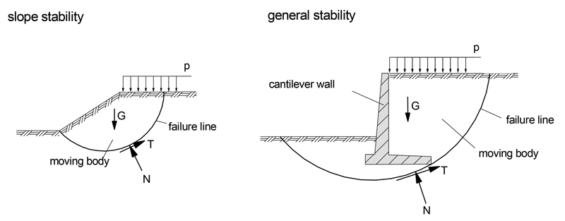
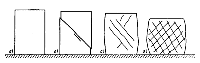
A loose soil is a structure composed of solid particles with pores and is therefore sensitive to shear stresses. The shear strength is defined as the soil’s ability to withstand shear stresses without failing and suffering plastic deformation. The following figure shows various fracture forms of cylindrical specimens, which were caused by a displacement within the grain structure on a sliding surface, i.e. the shear strength was exceeded. The shear stress on this sliding surface acts as a driving force, the normal stress on this sliding surface as a restraining force. The strength of the individual grains is exceeded only in very rare cases.
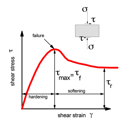
The following figure illustrates the mechanics of a soil specimen failing due to shear. After an initially approximately linear and elastic behavior, the nonlinear relationship between shear stress and shear strain begins until a maximum value of shear stress is reached. This is the value of the shear stress at failure, the shear strength, τf. It is required for calculations in earthwork constructions and foundation engineering. After a soil softening, the soil reaches a residual shear strength (large deformations!), τr .
The difference of the principal stresses, the deviator stress q = σ1 - σ3, is also used for the shear stress. The shear strength of a loose rock increases with the normal stress σ or with the isotropic stress component p = σm = (σ1 + σ2 + σ3 )/3; it decreases with the increase of the deviatoric stress component q.
Shear strength is composed of two components, friction and cohesion in the soil. It depends on the type and nature of the soil particles, the structure of the soil, the water content and its preloading conditions.
The shear strength τf is determined in shear tests according to DIN 18137. It increases with the magnitude of the normal stress acting in this loose soil skeleton.
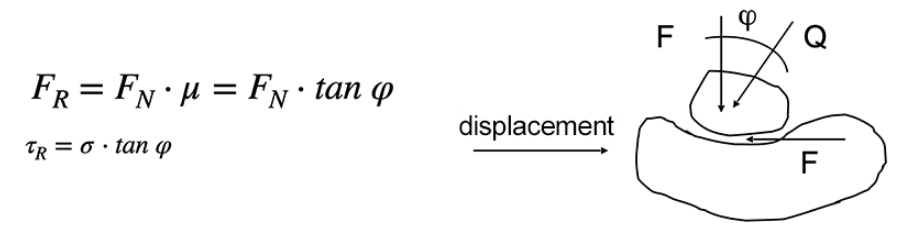
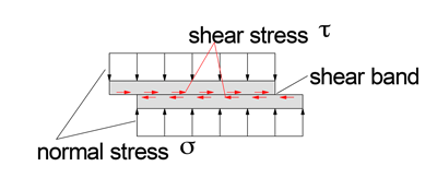
If granular soils are forced to move against each other, frictional forces become effective in a shear band. If cohesive soils are to change their position relative to each other, additional cohesive forces must be overcome in the shear band.
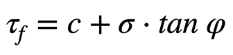
Coulomb formulates a linear relationship between the frictional force FR in the shear band and the normal force FN, or between the shear stress and the normal stress for soils in a joint where shear deformations occur:
However, cohesive soils with clay components develop additional adhesive forces, which are increased by surface tension of the water in the pores. These adhesive forces - cohesive forces - depend, among other things, on the clay minerals and the water content. The cohesive forces decrease with increasing water content and disappear at saturation.
Non-cohesive soils, e.g. moist sands, also possess adhesive forces between the individual grains. They are formed exclusively by the surface tension of the water. If this non-cohesive soil dries out or becomes saturated with water, these adhesive forces also disappear. These forces are called apparent cohesion. They should not be used in soil static calculations.
The shear strength τf as the maximum value of the shear stress in a given shear band in the limit state is therefore, taking into account the cohesion:
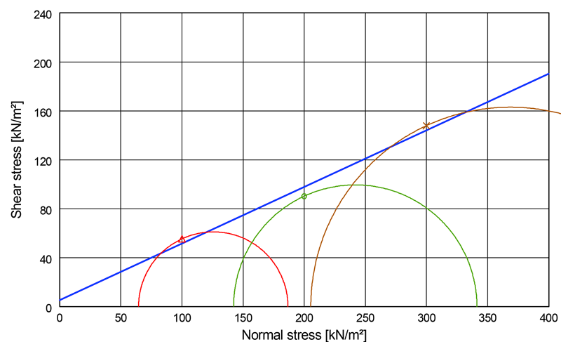
The limit stress state can also be described by the associated principal stresses. The relationship between the principal stresses σ1 and σ3 in the limit state is represented by the Mohr stress circle of the limit state. These principal stress circles have a common envelope for different values of the principal stresses. In soil mechanics, for limited stress ranges, this envelope is appropriately assumed to be a straight line, cf. the following figure. It is called Mohr-Coulomb failure hypothesis and is a tangent to the principal stress circles of the limit state.
1.1 Shear box apparatus
The shear strength can be determined with a shear box apparatus. A shear band is specified by the device and the test arrangement. The soil specimen is installed in a two-part box frame, the upper and lower parts of which can be moved relative to each other. The shear band therefore runs exactly between the upper and lower parts.
After applying a force normal to the shear band, the soil is consolidated, the water from the specimen drains through the filter stones. After this, either the shear force in the defined shear band is continuously increased or the box frame parts are displaced against each other at a constant speed with a constant normal stress.
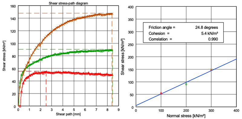
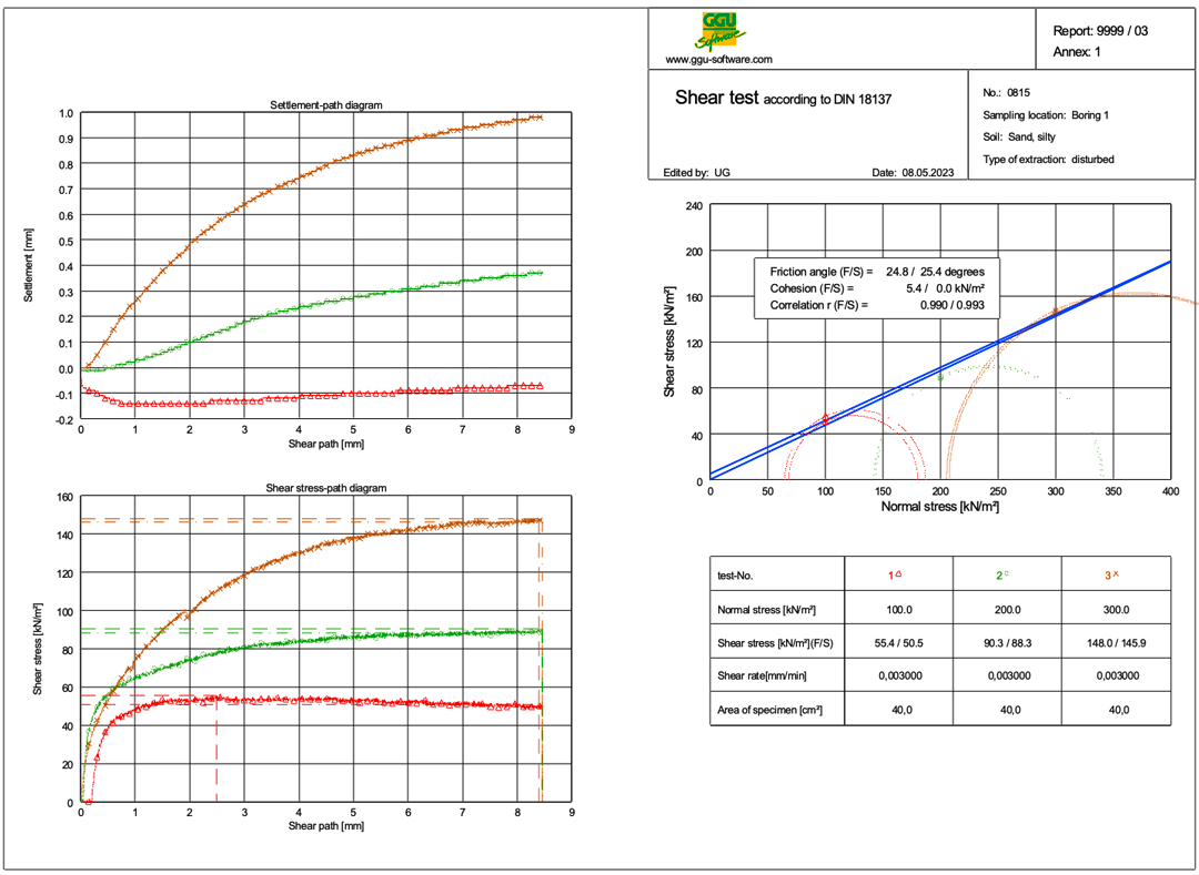
During the test, the shear force, the shear path and the normal force are continuously documented. The shear strength is given by τ = shear force/shear area and the normal stress by σ = normal force/shear area. Three individual tests provide the pairs of values for τ und σ, from which the shear diagram is generated.
From the shear diagram, the drained parameters c' and ᵠ' ( “ ’ " indicates a drained test) are then obtained as a pair of values, cf. the following figure:
Depending on the soil type, the shear diagrams differ. In the following figure, some soil types are qualitatively indicated with respect to their shear behavior.
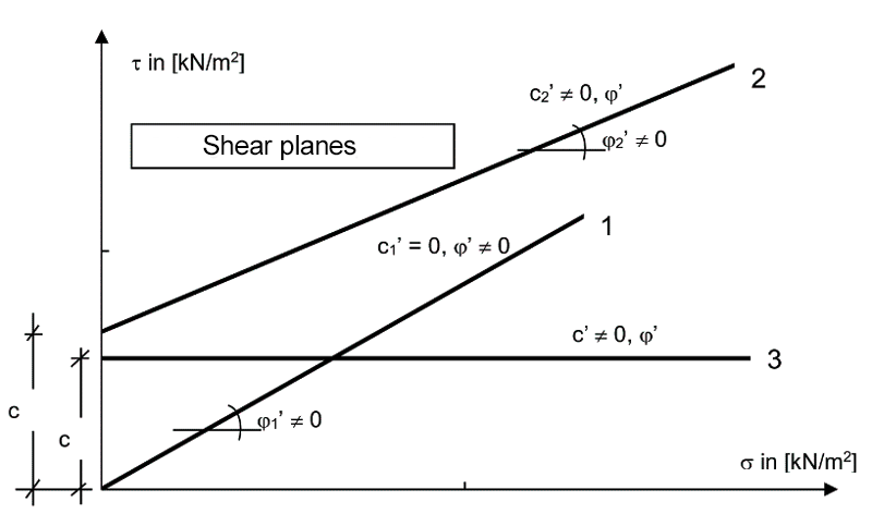
Shear plane 1 represents the result of a shear test for a non-cohesive soil, e.g. sand or gravel. Shear plane 2 shows results for a non cohesive soil with cohesive components. The soil develops an internal friction angle, but also shows cohesion, c2’ ≠ 0. The result of a shear test on a purely cohesive and unconsolidated soil is shown by shear plane 3. The soil does not develop an internal friction angle, but shows cohesion only.
1.2 Triaxial apparatus
In the triaxial apparatus, the soil specimen, enclosed in a rubber membrane, is placed in a cylindrical cell and subjected to an isotropic triaxial stress condition (σ1 = σ2 = σ3). Thereafter, the axial principal stress σ1 is increased until the specimen fails, while the cell pressure (σ2 =σ3) is kept constant.
Increasing σ1 is often done by constant increase in axial deformation or by gradually increasing the vertical load. The horizontal compressive stress σ3 is applied with a cell pressure.
The specimen is covered at its ends by filter stones through which the pore water can be drained and measured. In this way, the volume change of a water-saturated specimen can be measured, or the pore water pressure u that develops within the specimen during the test can be recorded.
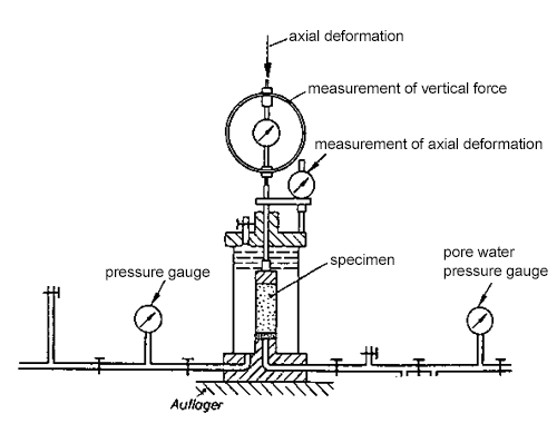

The following parameters are measured:
- the (all-round) cell pressure σ3
- the axial force, from which σ1 is calculated
- the deformation of the specimen
- if necessary the pore water pressure u.
The measured principal stresses are used to obtain the shear parameters ᵠ' und c:
Drained test (D test)
In this test, the deviatoric stress (shear stress-generating principal stress difference σ1 - σ3) is changed, but no pore water pressure remains in the soil specimen, because the excess pore water pressure dissipates by drainage (the finer-grained the soil, the slower the loading). Effective stresses are evaluated and thus the drained shear parameters ᵠ’ und c’ are determined.
Note:
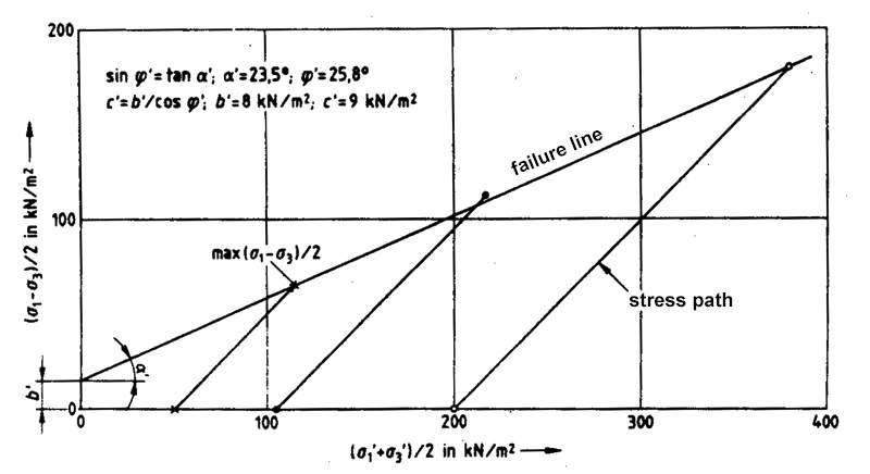
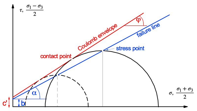
A distinction must be made between the shear planes (Coulomb envelopes) and the failure line. The failure line forms the connection of the stress points in the failure state. The fracture line has the angle α and has an "initial value" b. The shear plane (ᵠ‘,c’) represents the envelope of the stress circles and thus describes the shear parameters.
There are fixed relationships between the parameters b and c’ or α and ᵠ‘:
sin ᵠ’ = tan α’,
c’ = b’ / cos ᵠ’
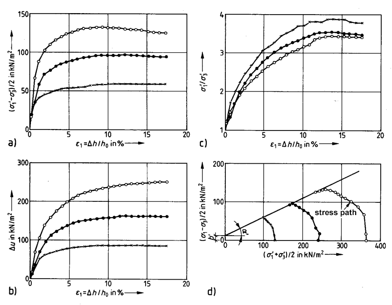
Consolidated undrained test (CU test)
Also in this test, the reduction of the excess pore water pressure is possible in the consolidation phase. As a result, an effective stress state prevails at the end of the consolidation. Subsequently, the specimen is sheared undrained while the pore water pressure is measured. Effective stresses (σ’ = σ - u) can thus be calculated and the associated shear parameters determined. Both, effective stress parameters ᵠ’ and c’ and total stress parameters ᵠu and cu can be determined.
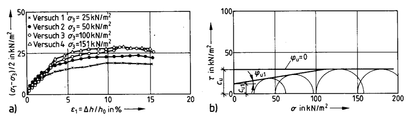
Unconsolidated undrained test (UU test)
Saturated specimen are set up in the cell and sheared to failure without consolidation. Effective stresses are present in the specimen, which are not affected even by the change in the all-round pressure. The pore water pressure increases during this process. During shearing, the pore water pressure may also decrease, depending on the stress history and saturation. With this test the undrained shear parameters ᵠu und cu are determined.
1.3 Uniaxial compression test
According to DIN 18136, cylindrical specimens are sheared under stress conditions σ2 = σ3 = 0 at constant speed. This results in the following fracture circle:
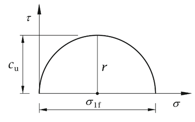
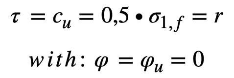
It is not possible to divide the shear strength into frictional and cohesive components. The shear strength of cohesive water saturated soils can be calculated as:
1.4 Vane
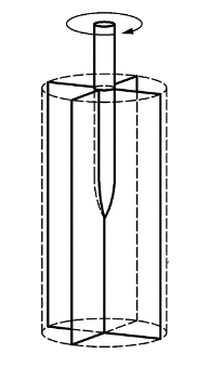
In both field and laboratory tests, the undrained shear strength can be determined with the aid of a vane in accordance with DIN EN ISO 2476-9. It is assumed that a uniform stress distribution is present at the surface of the cylinder and the end faces.
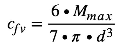
From the applied maximum torque and the diameter of the vane, the shear resistance cfv can be calculated with:
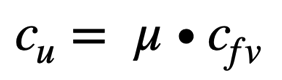
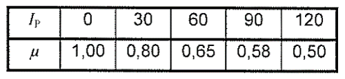
The undrained shear strength cu can be determined from the maximum shear resistance cfv, taking into account a correction value μ - depending, among other things, on the plasticity index Ip of the soil:
2. Shear parameters
The effective shear parameters ᵠ' and c‘ are parameters of the drained soil and are expressed by the limit state of the effective stresses. These parameters are used for the investigation of stability of non-cohesive soils or of consolidated states - of cohesive soils.
The shear parameters cu und ᵠu of the undrained cohesive soil are obtained from UU tests. They are called the total shear parameters. In the UU test, the water content does not change. In the CU test, it changes due to the drainage conditions. Therefore, different shear parameters cu und ᵠu result from both tests.
The parameter cu denotes the cohesion of the undrained, undrained soil. ᵠu is the friction angle of the undrained soil. cu depends on the one hand on the water content and on the shear rate.
The shear strength of an undrained cohesive soil is used as a basis for calculating the stability for the so-called initial state (t = 0) of a structure.
3. Analysis with GGU-DIRECTSHEAR
The computer program GGU-DIRECTSHEAR allows the evaluation and visualization of shear box tests and triaxial compression tests. In addition to entering only a value at failure and, if required, a slip value for each test, it is also possible to evaluate ASCII files supplied by shear box manufacturers.
Notes on use
All texts, images and media listed here are subject to copyright and are the intellectual property of Civilserve GmbH. Use is only permitted with appropriate reference and a link to this source.