Pile foundation
Table of contents
1. Pile foundations
Pile foundations are used if the ground directly beneath the structure to be founded is not load-bearing and the loads are to be transferred to deeper load-bearing subsoil layers. The type of load transfer depends on the subsoil and the condition of the piles.
1.1 Types of pile foundation, basic terms
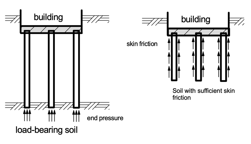
As shown in the next figure, a distinction is made between "standing piles", where the loads are transferred to deeper soil layers. "Floating piles", with a "floating foundation", transfer the loads to soil layers over the depth via skin friction, without, however, being founded on a load-bearing horizon.
1.2. Pile systems
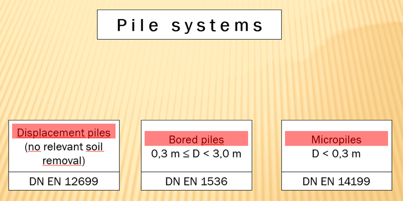
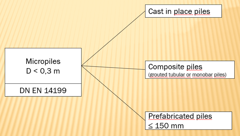
The various pile systems are grouped into three categories according to their design and possible applications: Bored Piles (DIN EN 1536), Displacement Piles (DIN EN 12699) and Micropiles (DIN EN 14199). Some of these pile systems are discussed in more detail below.
A further distinction by type of manufacture and material is shown below:
2. Pile types
In the following, some types of piles are presented without claiming to be complete. They are intended to provide an overview of the systems available on the market and their areas of application, as well as to show their application limits.
According to their type of manufacture, piles can be divided into prefabricated piles and in-situ piles or into driven, drilled and pressed piles according to their most frequently used method of installation. Possible systems are described in relation to their method of installation. An overview with advantages and disadvantages is given in the Geotechnical Engineering Handbook, part 3.
2.1. Displacement piles
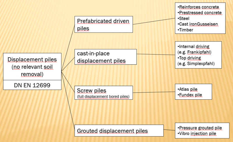
When the piles are installed, the existing soil is compacted and displaced laterally. By the compaction of the soil in the immediate vicinity of the pile, the bearing capacity is increased. According to EA-Pfähle (Recommendations of the working group "Piles"), displacement piles are divided into:
Prefabricated driven piles consisting of reinforced concrete, prestressed concrete, steel, cast iron or timber,
Driven cast in place displacement piles,
Grouted displacement piles and
Screw piles (full and partial displacement piles).
Reinforced concrete / prestressed concrete driven piles
Solid and hollow piles are used. Solid piles are made with slack reinforcement or with a prestressing. Possible cross-sections are square, rectangular, polygonal or jointed, with a square or circular cross-section usually being selected.
The cross-sections can be adapted to almost any static requirement, and almost any combination of cross-section, length and profile is possible during manufacture. Many connection possibilities with the building above are conceivable and are shown in the Geotechnical Engineering Handbook.
A disadvantage of this type of driven piles is their low load-bearing capacity in transverse bending. A heavy pile-driving rig is required for driving the piles into the ground, which involves great vibrations. If so-called coupling piles are used, they can be adapted to the soil mechanical properties of the soil with the resulting driving length during driving into the ground.
Prefabricated driven steel and cast-iron piles
Prefabricated steel driven piles are manufactured and installed as steel tubes or H-sections, as joined sections or sheet piles with a variety of cross-sections and wall thicknesses.
While steel tube piles are produced from commercial supplies (seamless or welded), joined section piles are produced by welding together several individual piles of common sheet piling systems. Steel tube piles are also used in mixed sheet pile walls by welding locks onto the walls and inserting filler piles.
All driven steel piles have in common that they can usually be driven into the ground without the formation of a wedged pile tip. In tubular or joined section piles, a driving plug is formed at the base of the pile, which has the same characteristics as a pile tip. However, to create this plug, it is often required that the piles be driven into the ground for the last 3 meters. If the pile is vibrated into the ground (by vibratory pile driving), the load-bearing capacity of these pile tips formed by soil will be reduced.
If symmetrically arranged steel sections are welded onto the steel pile used (box, tubular or H-sections) in the footing area, the load-bearing capacity of such a pile can be increased significantly. The shaft area is significantly increased, and a much larger driving plug can be formed between the individual sections at the base. The driving capability of the piles is hardly adversely affected by the welded sections, but the driving energy to be applied must be increased accordingly. The length of these welded-on sections depends on the type of pile and can have a length between 2 m and 3 m.
Steel piles have a high material strength combined with elasticity. They are insensitive during transport and can be extended during driving to suit the soil properties.
Analogous to the considerations and technical possibilities for driving sheet piles, the soils can also be classified according to their driving capability for driving the driven piles.
Cast-in-place displacement piles
Unlike the prefabricated driven piles presented in the previous two chapters, cast-in-place displacement piles, like bored piles, are produced directly at their final location. They are considered full displacement piles because they are driven into the ground under the protection of a closed-top tube until the load-bearing soil is reached. However, as the tube is pulled, the soil may relax slightly again. A well-known pile type is the “Frankipfahl”.
With the Franki pile driver, a tube is driven into the ground by means of free fall impact driving within the tube (internal driving). At the base of this tube a concrete plug, approx. 1 m high, is formed, which is strongly compacted by the tamping of the hammer. The plug drags the tube into the ground during further (internal) driving onto the plug. The soil is completely displaced and compacted, lateral stresses in the soil increase. Once the final depth is reached, the tube is held at its depth and the concrete plug is displaced from the pipe by further driving, thus forming an enlarged base installation. Further concrete of high plasticity is poured into the tube after setting a reinforcement cage and further compacted with internal driving. At the same time, the tube is withdrawn, creating a rough pile shaft. The result is a pile with a large pile base and with a large load-bearing capacity due to the compacted soil. Pile inclinations of up to 4:1 can be produced.
Prefabricated driven timber piles
Prefabricated driven timer piles should be briefly mentioned here for the sake of completeness. They have the advantage that they can be loaded immediately after driving into the ground and that they can be manufactured and installed in a previously known quality. If these piles are to be used permanently, they must be below the lowest groundwater or tidal water level. A simultaneous presence of oxygen and water causes the wooden piles to rot.
Pressure-grouted piles
A special type of driven piles is the pressure-grouted pile. Pressure-grouted piles are driven into the ground as a prefabricated pile with a wedge shaped enlarged pile shoe while adding grout. During driving the shoe forms an annulus around the steel shaft which is filled with cement grout during the installation process.
Displacement bored piles
Displacement bored piles are divided into partial displacement bored piles and full displacement bored piles. In the installation of these piles, a drill tube sealed at its tip is driven into the ground with an auger attached. The difference between the two methods is mainly in the method of recovery of the drill tube and with the associated amount of drill cuttings, and is described below. Both methods have in common that, due to the screwing of the drill pipe into the ground, they disturb the existing ground only insignificantly and can be used well in built-up areas due to lowest vibrations or noise generation during their production.
Screw piles - Full displacement bored piles
In the production of full displacement bored piles, the soil is completely displaced. The tube, which is closed at the bottom, is screwed into the ground. At the base of the tube there is a cutting head that ensures the helical driving of the tube into the ground. The soil in contact with the tube is completely displaced laterally, thus compacting it. When the target depth is reached, a reinforcement cage is placed and high plasticity concrete is poured in. The tube is recovered by unscrewing it, the tip of the cutting head remains in the ground and the concrete completely fills the void created by the cutting head. The finished pile shaft possesses a helical, concrete bulge and the completed pile resembles a screw.
In contrast to an Atlas pile, where only the sacrificial tip is lost in the soil after excavation, the tube of a Fundex pile is then withdrawn under oscillation, whereby the tip disengages from the tube. It remains in the ground and forms the pile base.
Partial displacemenet piles
In the partial displacement drilling method, a continuous hollow auger is rotated to the target depth, which is sealed watertight at the lower end foot plate. In the process, the soil surrounding the hollow auger is displaced. Partial drill cuttings take place through the helix applied on the outside.
When the hollow auger has been lowered into the load-bearing soil, the reinforcement cage is placed and concrete is pumped in while the hollow auger is being pulled. The base plate remains in the ground.
In this way, piles with a diameter corresponding to the outer diameter of the helix are produced.
2.2. Bored piles
Bored piles transfer loads into the ground through a combination of skin friction forces and peak pressure. Bored piles are also well suited for absorbing bending moments and horizontal forces.
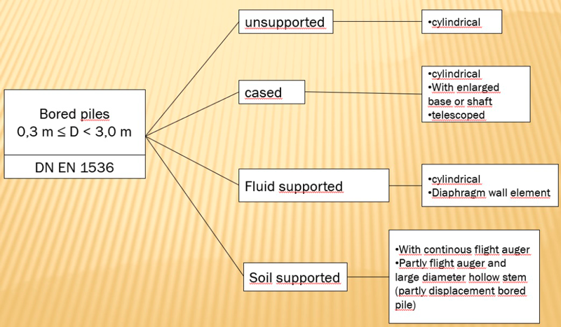
Bored piles belong to the group of in situ piles. Boreholes are produced through a casing, open at the bottom. After placing reinforcement cages, concrete is poured into the cased void. For working in groundwater, hydrostatic force must be used. Bored piles can be produced:
- unsupported,
- cased,
- fluid supported and
- soil supported (with continuous auger).
The production of bored piles is largely vibration-free and can therefore be carried out in the immediate vicinity of the existing development. The length of the pile can be adjusted to the soil during production and can be drilled into the ground to great depths. They can be manufactured up to a slope of 4:1 (~15°) against the vertical axis.
Bored piles transfer loads into the ground via a combination of skin friction pile end bearing resistance. Bored piles are also well suited for bearing bending moments and horizontal forces.
2.3. Micropiles
Tubular grouted piles
Tubular grouted piles are micropiles with a diameter of less than 30 cm according to DIN EN 14199, which transfer their load almost exclusively via skin friction into the surrounding soil. The load-bearing elements of micropiles can either be set in a previously drilled borehole and then grouted with cement slurry or produced as a self-drilling element with cement flushing. As small-diameter composite piles, micropiles are designed with a tubular or bar-shaped steel support member - and with a cement mortar coating.
Press piles
Pressed piles are also used to construct an underpinning for an existing building where the available working space is limited. Individual sub-segments can be connected together to form a complete system when pressed into the ground. These pressed piles must bind into the load-bearing subsoil.
Pressed piles can consist of individual steel pipe segments that are filled with in-situ concrete. The individual segments are welded together before the next section is concreted out again after setting a reinforcement. When the required press-in force is twice the live load, the press-in process is terminated.
3. Pile foundation design
Piles must be able to transfer their loads safely into the load bearing soil. On the one hand, the pile loads must be able to be carried without inadmissibly large settlements (external load-bearing capacity), and on the other hand, the piles themselves must be able to bear the loads (internal load-bearing capacity). The following pictures are intended to illustrate the load-bearing behavior of piles in the ground:
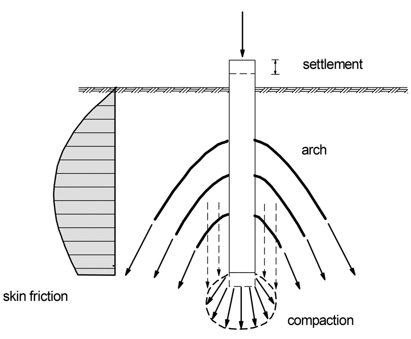
A force is transferred into the load bearing soil via skin friction at the pile shaft and the end pressure in the area of the pile toe:
- The skin friction results from shear stresses between the pile shaft and the surrounding soil and is influenced by the shear strength of the soil, the roughness of the pile surface and the magnitude of the normal stress acting perpendicularly on the pile shaft. Due to the increased stresses in the soil during the construction of a driven pile, the skin friction is therefore greater than for a bored pile. The magnitude of skin friction therefore strongly depends on the selected production method and cannot be determined using earth pressure approaches. Experience values or measurements must provide reference values for a design. Only very small deformation paths (in the mm range) are required to activate the full skin friction.
- End pressure refers to the base stress under the pile toe. The end pressure can reach considerably larger values than those of skin friction. In driven piles, these values are activated after settlement of only a few millimeters. In the case of bored piles, this can be several centimeters due to the manufacturing process.
The ratio between end pressure and skin friction depends on the pile diameter, the pile length, the magnitude of the load and the surrounding soils. The greater the settlement, the greater the share of peak pressure, cf. the following figure.

The external bearing capacity is calculated by determining the possible pile resistance, consisting of skin friction and end pressure.
3.1. Bearing Capacity and Resistances of Axially Loaded Piles
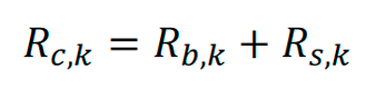
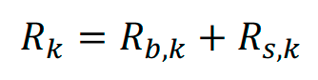
When determining pile resistances, a distinction is made between compression and tension piles. The resistance of compression piles Rc,k is composed of pile end bearing resistance Rb,k and skin friction Rs,k:
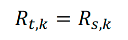
The resistance of a tension pile Rt,k consists only of the skin friction Rs,k:
The total resistance results from the resistance-settlement or resistance-heave curves. According to EC 7 and Recommendations on Piling (EA-Pfähle), this can be derived from load tests, from empirical values or from comparable pile load tests, whereby the resistance-settlement curve from empirical values can only represent a preliminary dimensioning.
Pile loads tests provide reliable results and are to be carried out at representative test locations with regard to the ground conditions. Both static and dynamic pile load tests are possible. The evaluation of the pile test loads is regulated in EC 7 and in the Recommendations on Piling (EA-Pfähle).
3.2. Axial pile resistance for bored piles based on empirical data
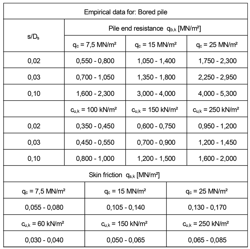
If, in the course of the design, load tests of piles are not carried out - e.g. for economic reasons - and no further knowledge is available and if no further knowledge is available, the design of bored piles can be carried out with the help of table values from the Recommendations on Piling (EA-Pfähle). The determination of pile resistances from empirical values is regulated in the Recommendations on Piling (EA-Pfähle). The ranges for the empirical values are documented there, of which the smallest value (lower values) is to be used as a rule, shown as an example for a bored pile in the following table:
The Recommendations on Piling regulates that the larger pile resistance values within the specified range or other empirical values, e.g. from comparable test loads, may only be applied if they are explicitly confirmed by an expert in geotechnical engineering.
The following criteria must be met for the application of these values:
- thickness of the load-bearing layer below the pile base ≥ 1.5 m and ≥ 3 ⋅ Db (pile base diameter).
- the following must apply to the load-bearing layer under the pile foot:
for non-cohesive soils, the cone penetration resistance qc of the cone penetration test (CPT) must be at least 7.5 MN/m² or,
for cohesive soils, the shear strength of the undrained soil cu,k must be at least 0.1 MN/m²
- the minimum embedment depth in a load-bearing layer must be at least 2.5 m
- the pile diameter Db is greater than 0.3 m and less than 3.0 m

The characteristic pile resistance Rk is composed of the components of the pile end bearing resistance Rb,k and the pile skin resistance Rs,k. As described, these quantities depend on the pile’s settlement.
In order to be able to determine the pile end bearing resistance Rb,k with the help of the empirical values, the cone penetration resistance qc must be known for non-cohesive soils and the undrained shear strength cu,k for cohesive soils. Tables 5.12 and 5.14 of the Recommendations on Piling (EA-Pfähle) give the values for the pile end resistance qb,k as a function of qc and cu,k and a related pile head settlement s/Db necessary for the calculation.
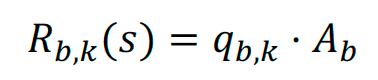
For the related settlement of 2%, 3% and 10% of the pile diameter, the tables give the corresponding pile end resistance qb,k, which can be used to calculate the pile end bearing resistances Rb,k for the pile toe area Ab:
Using Tables 5.13 and 5.15 of the Recommendations on Piling (EA-Pfähle), which give the pile skin friction qs,k as a function of the cone penetration resistance qc for noncohesive soils and the undrained shear strength cu,k for cohesive soils, respectively, the characteristic activatable pile skin resistance Rs,k can be calculated.
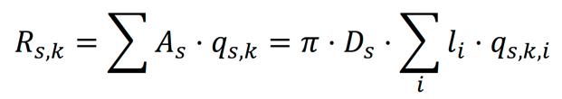
For all soil layers of a stratified soil, the characteristic activatable pile skin resistance Rs,k is calculated as the product of the skin area As embedding in these layers and the pile skin friction qs,k.
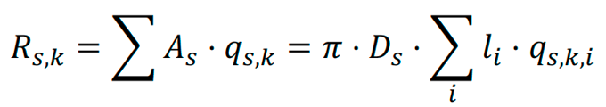
with
Ds = pile shaft diameter
li = embedment length in stratum i
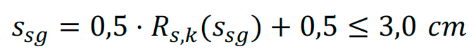
The pile skin resistance is increasingly activated as pile settlement occurs. At the so-called limit settlement ssg, the resistance has reached its maximum value and does not increase with further settlements. This equation is not true to the unit, Rs,k is inserted into the equation in [MN], ssg is a quantity with the unit [cm].
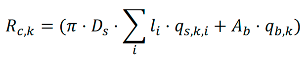
From both parts (pile end resistance and pile skin resistance) the characteristic value of the pile resistance for to is obtained:
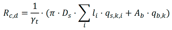
The design value can be obtained:
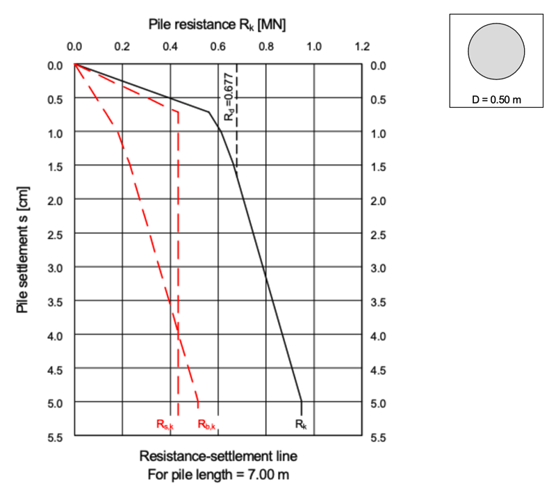
With the calculated values, a resistance-settlement curve is now determined (for actions from tensile forces: resistance-heave curve). The characteristic pile end resistance Rb,k(s) results from a polygonal traverse as a function of the pile settlement related to the pile diameter Ds. A linear progression is assumed between the resistance values at the specified settlements of 2%, 3% and 10% of the pile diameter Ds. From a pile head settlement of sg = 0.1 Ds, the pile end resistance is no longer expected to increase, i.e. it has its maximum value there, the resistance-settlement curve runs vertically from this point in the diagram. A pile end widening can be considered in the entire calculation with the diameter of the pile end widening diameter Db.
3.3. Axial pile resistances based on empirical data, prefabricated driven piles
Prefabricated driven piles may also be designed using empirical values in the event that no results of load tests are available. The empirical values found in the tables apply to circular pile cross-sections. For rectangular or square piles, an equivalent pile cross-section is calculated as follows:
Deq = D (circular piles)
Deq = 1.13 ⋅ as ( square piles)
Deq = 1.13 ⋅ as ⋅ ![]() (rectangular piles or steel girder sections)
(rectangular piles or steel girder sections)
with
as = pile width for a square piles or pile width of the smaller side of the pile
aL = pile width of the larger side of the cross-section for rectangular piles. For steel girder sections, the circumferential length of the pile tip applies.
The settlement dependent pile end resistance Rb,k is calculated for the pile head settlements
s = 0.035 ⋅ Deq and sg = 0.10 ⋅ Deq:
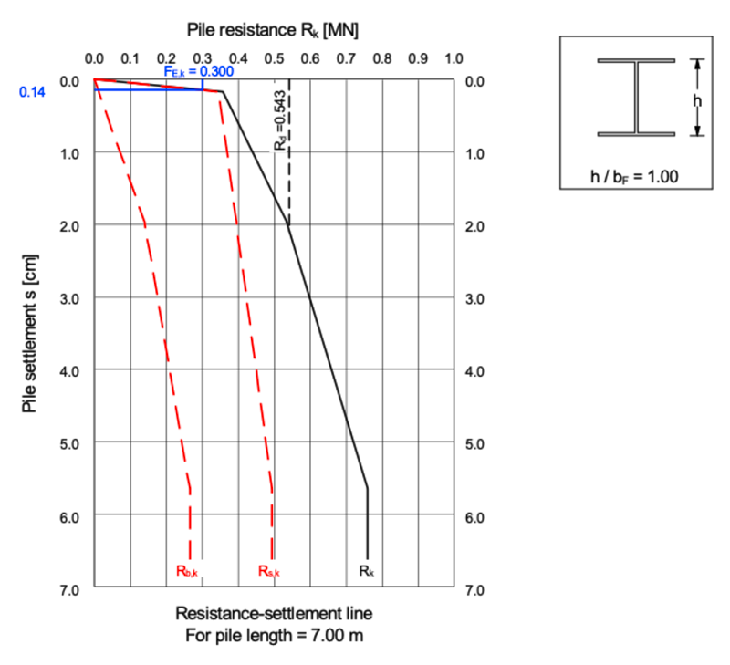
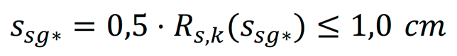
When mobilizing the ultimate limit state, the characteristic settlement for Rs,k (ssg* ) is calculated using the following equation:
The characteristic axial pile resistance is determined from:
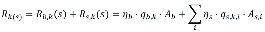
with
Ab = nominal pile base area
As,i = nominal pile shaft area in stratum I, for steel section piles with the circumferential length
qb,k = characteristic value of the pile end resistance (Tables. 5.1, 5.3, EA-Pfähle)
qs,k,i = characteristic value of the skin friction in stratum i (Tables. 5.2, 5.4, EA-Pfähle)
ηb = pile end resistance model factor (Table 5.5, EA-Pfähle)
ηs = skin friction model factor (Table 5.5, EA-Pfähle)
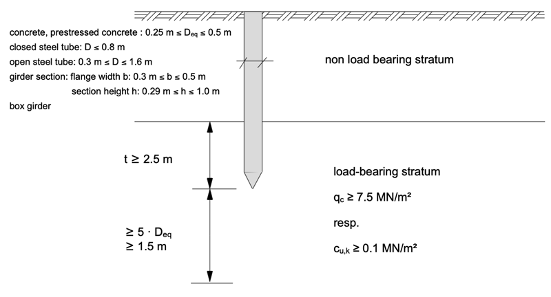
The following criteria must be met for the application of these values:
- thickness of the load-bearing layer below the pile base ≥ 1.5 m and ≥ 5 ⋅ Db (pile base diameter)
- the following must apply to the load-bearing layer under the pile foot:
- for non-cohesive soils, the cone penetration resistance qc of the cone penetration test (CPT) must be at least 7.5 MN/m² or,
- for cohesive soils, the shear strength of the undrained soil cu,k must be at least 0.1 MN/m²
- the minimum embedment depth in a load-bearing layer must be at least 2.5 m
- the pile diameter Ds is greater than 0.25 m and less than 0.5 m. For rectangular or square piles, an equivalent pile cross-section can be calculated.
3.4. Axial pile resistances based on empirical data for Franki piles
The design of Franki piles is somewhat different from the design of the other piles discussed in the Recommendations on Piling (EA-Pfähle).
The design value of the effects of actions Ed results from characteristic actions
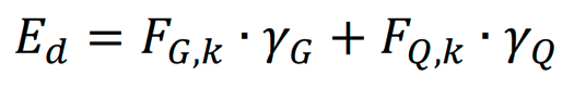
with
γG = partial safety factor for permanent actions
γQ = partial safety factor for variable actions
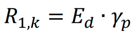
With the partial safety factor for pile resistances the necessary characteristic pile resistance R1,k can be obtained:
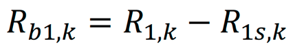
The necessary characteristic pile resistance R1,k is composed of the skin friction resistance R1s,k and the pil end resistance R1b,k. The characteristic value of the skin friction resistance can be calculated with the values given in tables 5.10 and 5.11 respectively, whereas the skin friction is only adopted from 0.8 m above the driving depth. The necessary pile end resistance R1b,k can be calculated with:
Using the averaged values for the cone penetration resistance qc or for the shear strength of the undrained soil cu,k and the required pile end resistance R1b,k, the required pile base volume V can now be determined from the Figs. 5.5 to 5.10 of the Recommendations on Piling (EA-Pfähle).
However, it is expressly pointed out that the pile base volume determined in this way serves only for a preliminary design. The ultimate limit state is to be verified with the driving work performed on the last two pile meters, cf. the notes in EA-Piles 5.4.5.3.
3.5. Other pile systems
For the determination of the pile resistances of other pile systems, such as
- Simplex piles
- Atlas piles
- Fundex piles
- grouted displacement and micropiles
empirical values for the calculation of axial pile resistances are given in the Recommendations on Piling (EA-Pfähle).
3.6 Tension piles resistances
EA-Pfähle requires: “Because generally accepted methods for analysing pile resistances are not yet developed, the EC 7-1 Handbook requires that pile resistances shall normally be determined on the basis of pile test results. It is also permissible to determine axial pile resistances on the basis of empirical data (5.4), which should, however, also be derived from pile load tests.
If, in well-founded, exceptional cases, tension piles resistances based on empirical data are adopted, the derived characteristic skin friction values must be confirmed by a geotechnical expert or geotechnical designer for the specific situation. In this case it shall also be checked if the empirical data given in the above tables should be further and considerably reduced for deriving tension pile resistances, e.g. by applying appropriate calibration factors.”
The following applies to a preliminary structural analysis under the conditions described above: Tension piles do not activate end bearing resistance. The (tensile) loads can only be transferred via skin friction. Using the empirical values for skin friction coefficients qs,k given in the Recommendations on Piling (EA-Pfähle), possibly reduced by a geotechnical expert, the characteristic activatable pile skin resistance Rs,k can be calculated as the product of the skin area As in stratum I and the characteristic value of the skin friction in stratum i qs,k:
with
Ds = pile shaft diameter
li = embedment in stratum i
The limit heave can be calculated with:

In analogy to the compression piles, a resistance-heave curve can be constructed. From this, the characteristic pile resistances R1,k and R2,k can be determined:
- characteristic pile resistance R1,k in ultimate limit state (GEO-2) at limit heave sg,tension
- characteristic pile resistance R2,k in the serviceability limit state (SLS) at the maximum allowable heave s2
It is necessary to investigate whether the sum of unfavorable actions is smaller than the sum of permanent favorable actions.
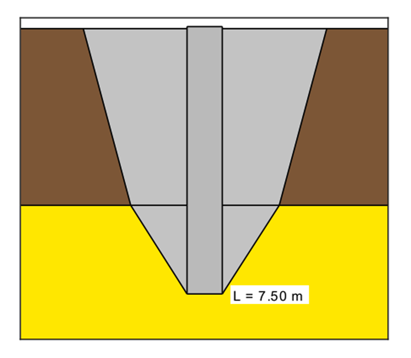
In addition, it must be verified whether the soil "hanging" on the piles is capable of bearing the tensile force. The volume of this earth body is calculated as shown in the following figure.
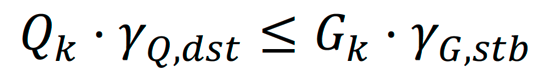
with
Qk = characteristic tensile action
γQ,dst = partial safety factor for unfavorable variable actions
Gk = characteristic value of the soil weight
γG,stb = partial safety factor for favorable permanent actions
The load bearing capacity of tension piles shall always be verified on site by load tests.
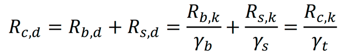
3.7. Design value of axial pile resistances
The design value of the load bearing resistance of compression piles can be obtained:
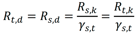
The design value of the load bearing resistance of tension piles can be obtained analogous:
with
γb, γs, γt = partial safety factors for compression piles
γs,t = partial safety factors for tension piles
The serviceability limit state (SLS) is verified with characteristic quantities. The partial safety factors have the value 1.0. This verification ensures that the deformations of a pile under service loads do not exceed a certain limit of settlements.
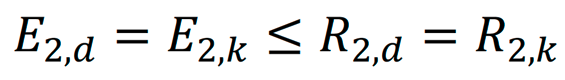
with
E2 = effect of actions for the serviceability limit state (SLS)
R2 = pile resistance for the serviceability limit state (SLS)
3.8. Analysis of pile groups
In pile groups the distribution of the total of the actions on individual piles is not distributed uniformly in a pile group. In compression pile groups, for example, the corner piles are usually the most heavily loaded.
The pile resistance of pile groups can be calculated using resistance-related group factors and the pile resistance of a comparable individual pile. An approximate method with nomograms for determining the settlement-related and resistance-related pile group behavior is given in the Recommendations on Piling (EA-Pfähle)
4. Laterally loaded piles
The bearing capacity of long, flexible piles in the governing design situation in the ultimate limit state (ULS) situations STR and GEO needs not be analysed if the piles are embedded in the ground and the horizontal characteristic effect in the DS-P design situation is no more than 3 % of the vertical effect, or 5 % in the DS-T design situation.
Proceed as follows for all other cases according to EC 7 and Recommendations on Piling (EA-Pfähle) respectively:
- definition the input values for determining ground reactions, e.g. a modulus of subgrade reaction
- determination of the characteristic action effects or the characteristic stresses using the characteristic values of actions and the characteristic values of the subgrade reaction moduli
- verification that the characteristic normal stress σh,k along the pile shaft between the pile and the ground does not exceed the characteristic passive earth pressure eph,k calculated for the two dimensional situation:
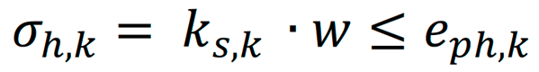
- the analysis using the above equation assumes in approximation that only a stress comparison is required, which involves the normal stresses σh,k between the pile and the ground, calculated using the modulus of subgrade reaction method, and the two dimensional characteristic passive earth pressure stresses eph,k in front of the pile, calculated according to EC 7-1. EC 7-1 does not stipulate that a displacement-dependent mobilization of eph,k be considered. The passive earth pressure stresses eph,k are introduced here only as maximum normal stress limits σh,k. The numerical reduction to the two dimensional passive earth pressure (and not to the three-dimensional case) provides safety reserves with depth, which depend on the utilization. The analysis relates primarily to calculations using the approximation approach for determining internal forces:
- If pile load test results are available, realistic, if necessary non-linear, modulus of subgrade reaction variables and distributions should be derived from them for the ground resistance, as a function of the load ranges.
- verification that the lateral ground resistance Bh,d was not adopted at greater than allowed by the design value of the three-dimensional passive earth pressure Erph,d for the corresponding component of the embedment depth as far as the pile pivot (displacement zero point):
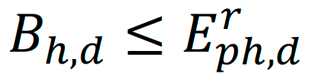
- analyse safety against structural failure
A program solution to the problem is to solve the differential equation of the elastically bedded pile (bending beam) for the given boundary conditions:
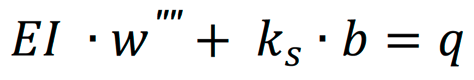
mit
E = modulus of elasticity
I = moment of inertia
w = displacement of pile
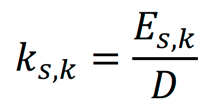
ks = modulus of subgrade reaction
b = pile width
q = action (load)
The solution is determined numerically. Among other things, the so-called finite element method is used.
5. Example of the use of the computer program GGU-AXPILE
For the bored pile shown below, with a diameter of 50 cm and a length of 10 m with a permanent load of PG = 0.5 MN and a variable load of PQ = 0.2 MN the following video shows how the analysis can be carried out using the computer program GGU-AXPILE.
6. Example of the use of the computer program GGU-LATPILE
For the prefabricated driven steel pile with an H-section shown below, with a length of 6.5 m with permanent and variable actions of MG / MQ = -50 / -20 kNm and HG / HQ = -20 / -10 kN (signs according to program definition) the following video shows how the analysis can be carried out using the computer program GGU-LATPILE. The modulus of subgrade reaction is assumed constant along the whole pile shaft.
Notes on use
All texts, images and media listed here are subject to copyright and are the intellectual property of Civilserve GmbH. Use is only permitted with appropriate reference and a link to this source.