Lowering of the groundwater table
Table of contents
1. Dewatering
In the presence of groundwater an excavation pit will fill with water. Some time after the excavation, the groundwater table at rest will be reached. To guarantee a dry excavation pit, the groundwater table of the inflowing water can be lowered by continuous pumping with the aid of a dewatering system.
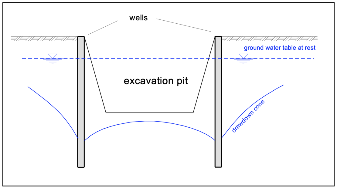
Depending on the permeability of the soil, a gradient of varying degrees is created between the lowered and the groundwater level at rest during dewatering. If the existing soil has a large pore volume (high permeability), the flow resistance is small and a very shallow gradient is formed. If the pore volume is small, the flow resistance is greater and so is the slope. Depending on the permeability, suitable methods for dewatering must be selected.
Open drainage
Open drainage (dewatering with pumping from wells, slits or drainage sumps) is the simplest method. The groundwater flowing into the excavation pit is collected and pumped away together with any rainwater that may occur.

In case of the water surface exiting the excavation’s slope supporting filters have to be arranged. The supporting filter material must be adapted to the surrounding soil in order to prevent erosion (material transport). For this purpose, DIN 4095 requires the application of the filter rule according to Terzaghi with "D" as the grain diameter of the filter material and "d" as the grain diameter of the material to be filtered:

Gravity drainage
In gravity drainage, the water flows to the well due to its gravity caused by the difference in water level. The hydraulic gradient is created only by gravity.
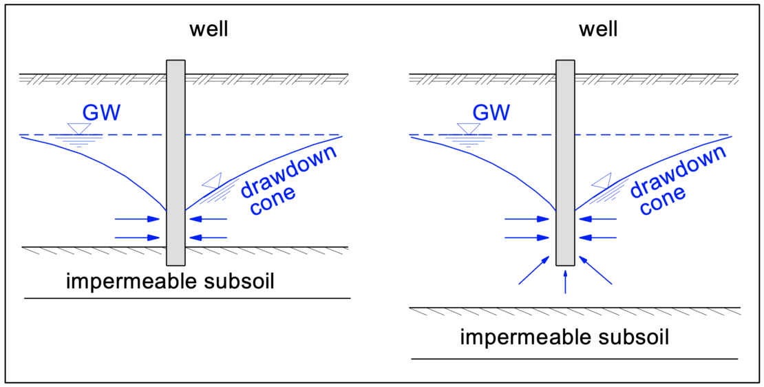
Depending on the ground conditions, a distinction is made between perfect and imperfect wells. Perfect wells are standing on an impermeable subsoil. The influx therefore only occurs horizontally. Imperfect wells end within the aquifer. Additional water influx from below must be taken into account in the design as shown in the figure above.
Shallow wells
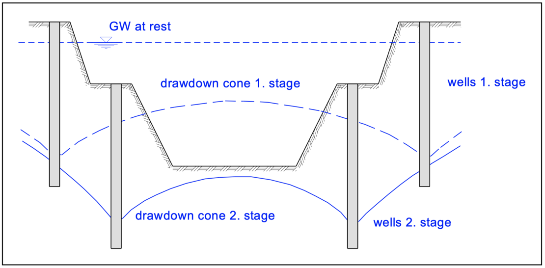
With shallow wells (e.g. centrifugal pumps with a maximum suction head of 8 m), the water level below the base of the excavation pit can only be lowered by a small amount, depending on the dimensions of the excavation. If this is not sufficient to drain the excavation pit, dewatering systems can be designed as stages of well point galleries. Due to the berms for each stage, the excavation pits become very wide.
Deep wells
In deep well systems, an electrically operated pump is installed in each well, which forces the water to the surface rather than sucking it to the surface. The pumping head is thus not limited, any drawdown level becomes possible.
Deep wells are built to the required depth plus the design height of the pump. A filter tube with slots sits on top of the sump tube and the extension tube sits above it. The filter tube is surrounded by a package of filter gravel to prevent material transport from the surrounding soil. The filter material is again to be determined according to Terzaghi's filter rule.
Vacuum wells
For fine graded soil types where gravity is not sufficient for the water to flow to the well, a vacuum system must be used to draw the water to the well. For this purpose, a vacuum must be built up, which is transferred to the subsoil. The water held to the fine grains by adhesion is made to flow by the applied hydraulic gradient. However, only that part of the vacuum can be transferred to the soil that does not lift the water to the surface.
Available are suction lances installed by jetting, which receive the vacuum from one suction hose only, and vacuum supported deep wells, which draw the water to the well with the help of a vacuum and lift the water to the surface with another submersible pump.
Suction lances represent the simplest form of shallow vacuum wells. The filter tube of the system also serves as a suction tube and is directly connected to the suction hose. Because of the small values of the lowering of the ground water table, the suction lances should be arranged at a distance of 1 m to 2 m from each other. The pumped water quantities are small.
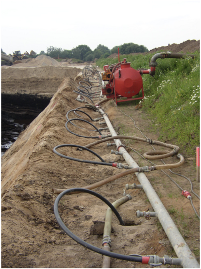
Photo: Glabisch
Vacuum deep wells are used when limited space does not allow the use of staging systems. The water is drawn to the well with a vacuum and raised to the surface with another submersible pump.
Dewatering by electro-osmosis
The electro-osmosis method uses an electrical potential gradient to direct water to the cathodic well and then pump it out. This method is used for soils that have a coefficient of permeability of kf = 10-7 m/s and smaller and where other drainage methods fail.
The water migrates from the anode towards the cathode due to the electrical potential gradient. The amount of water collected in this way is very small. Regular steel sections are used as the anode, and the vacuum wells themselves are formed as the cathode. This method is very expensive and is very rarely used.
2. Dewatering by bored wells
Discharge of a rotationally symmetrical single well
When water is drawn from a well, a hydraulic gradient forms between the water level in the well and the groundwater level at rest. The groundwater flows to the well in a funnel shape (rotationally symmetrical).
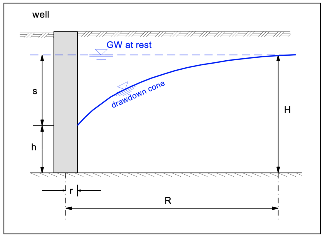
The water discharge to a perfect rotationally symmetric well is calculated with:

Well capacity of a rotationally symmetric single well
According to Sichardt, the well capacity is defined as the amount of water that a well is able to hold per unit of time through its filter area, assuming that the largest hydraulic gradient i0 in the ground occurs at the filter tube of the well. Sichardt establishes a relationship between the maximum hydraulic gradient at the filter tube i0 and the permeability of the surrounding soil. Thus, the maximum capacity of a single well is calculated with:

Comparison of discharge and well capacity
The equations for the discharge and for the well capacity are a function of the height h of the influx surface of the filter (the wetted filter surface). Thus, the capacity Q’ is linearly and the discharge quantity Q parabolically dependent on this height h. With the determined water discharge Q flowing into the well, it must now be checked whether the capacity Q' of the well is sufficient to hold this water quantity.
Thus, for each calculation, it must be verified that the capacity is equal to or greater than the influx to the well.
Radius of influence
Sichardt establishes a well-known approximate formula for determining the radius of influence, which is not dimensionally accurate:

Further equations for calculating the radius of influence R are presented by Kussakin and Weyrauch, among others. According to Weber, the influence of the so-called equivalent radius A (see below) must be taken into account for small values of the permeability with a low drawdown and large excavation pits:

Group of bored wells
For the dewatering of an excavation pit, a group of bored wells is used to keep it dry for the construction period. The following picture shows an example of the arrangement of wells along the edges of the excavation pit.
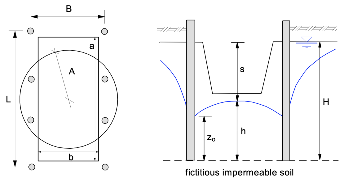
For the calculation of a group of bored wells, an equal-area equivalent radius A is calculated from the area B X L (formed by the adjacent wells). This equivalent radius A represents the radius of an equivalent well with the total capacity of all individual wells of the considered group well system. Thus, the influx to a perfect equivalent well can be described by the following equation:


The water surface at any location is obtained with the help of the formula for a group of perfect wells according to Forchheimer. After conversion of the equation for the calculation of the total influx to all single wells of a group of perfect wells for n single wells with a known total discharge Q with
x1, x2, ..., xn : distances of the individual wells from an arbitrary point
the water surface level "y" can be determined at any point P, taking into account the effect of all individual wells at their distances xi from the point P under investigation:

General procedure for the dimensioning of a group of bored wells
- Determination of the discharge Q required for drawdown:
- determination of the water level drawdown target s and the well depth based on the boundary conditions,
- determination of the equivalent radius,
- estimation of the radius of influence R and discharge Q required to reach the drawdown target s,
- selection of the number of wells n and determination of the well arrangement,
- checking the drawdown target s in the most unfavorable locations. If the drawdown target s is not achieved, either the well arrangement or number must be adjusted or the discharge must be increased.
- Dimensioning of the wells:
- determination of the well with the greatest drawdown,
- selection of the well radius,
- check if the capacity q' of the individual wells is sufficient to pump the determined discharge q.
3. Example of the use of the computer program GGU-DRAWDOWN
For the excavation pit shown (ground level: 37.4 m NN), the groundwater drawdown is to be calculated using the computer program GGU-DRAWDOWN. The groundwater level is at 35.4 m NN.
According to the following sketches, this is an excavation pit with the dimensions a / b = 20 m / 12 m. The target groundwater drawdown is s = 6.5 m. The wells with a radius of r = 0.2 m are placed at a distance of 1.0 m from the edge of the excavation. The distance H between the ground water level at rest and the wells’ base is assumed to be 12 m. The permeability of the soil is given as kf = 1 • 10-4 m/s.
Notes on use
All texts, images and media listed here are subject to copyright and are the intellectual property of Civilserve GmbH. Use is only permitted with appropriate reference and a link to this source.