Diaphragm walls
Table of contents
1. Diaphragm walls
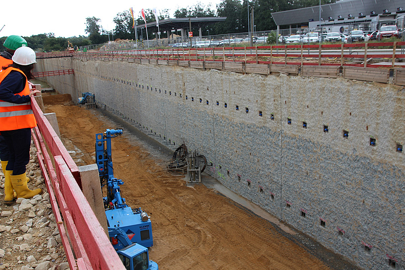
Diaphragm walls can be chosen as a variant of cast-in-place concrete retaining walls. Diaphragm walls represent watertight low-deformation retaining walls which are capable of transferring large vertical loads into the ground, but also of supporting horizontal loads due to their high flexural stiffness. Deep excavation pits and the immediate vicinity of buildings are the favorite areas of application for this type of retaining walls, not only because of the very low deformations, but also because of the low-vibration production. If the stiffness is not sufficient, anchors can also be used to increase the load-supporting capacity as shown on the following photo.

2. Wall construction method
A diaphragm wall is a retaining wall made of reinforced concrete in a trench in the ground supported by a thixotropic fluid using the tremie process. In this case, it is called a cast-in-place diaphragm wall. If precast elements are placed in the supporting liquid, it is called a precast diaphragm wall. DIN EN 1538 (“Execution of special geotechnical works – Diaphragm walls”) describes the production process. Basically, a distinction can be made between the two-phase and the single-phase construction technique:
With the two-phase construction technique, the soil excavation for a cast-in place concrete diaphragm wall is carried out under a non-self-hardening supporting fluid. This supporting fluid (1st phase) usually consists of water and a clay (bentonite) slurry, although in certain cases a polymer liquid is used.
After reaching the final depth and inserting the stopend elements or joints, as well as after inserting a reinforcement cage, the supporting liquid is displaced and replaced from the bottom to the top by the concrete placed by the tremie process (2nd phase). The tremie process is used for all reinforced walls, but also for non-reinforced cut-off walls. Excavation of the diaphragm wall can be carried out using either rope grabs or cutters.
With the single-phase method, a self-hardening cement-based suspension with possible additives as e.g. clay (bentonite), fly ash, stone powder, etc. is used as the supporting liquid. The suspension is no longer replaced. Using the single-phase method reinforced diaphragm walls can no longer be constructed as cast-in-place concrete walls, but are produced by inserting precast reinforced concrete elements into the hardening suspension (combination method). This method is usually used for sealing cut-off walls.
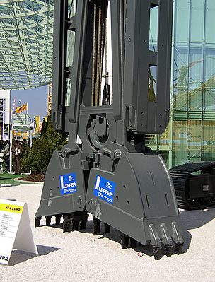
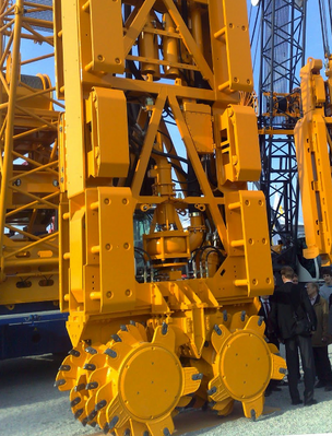
Diaphragm wall cutters and rope grabs, which are shown in the following pictures, are used to excavate the trench with a guide wall at the top end of the wall to guarantee the construction accuracy by controlling line and level of the trench.


3. Static systems
Static systems are used to calculate internal forces and state variables, which depend on the selected embedment depth and anchors or struts in one or more planes:
- unsupported wall, fully fixed earth support
- single / multiple supported wall with free earth support
- single / multiple supported wall, fully fixed earth support
- single / multiple supported wall, partially fixed earth support
The calculation of diaphragm walls can be carried out according to several procedures. The classical methods refer to the earth pressure theory and thus vary depending on the static system with regard to the magnitude and distribution of the earth pressure and the reaction forces in the soil. Basic systems are single or multiple supported beams that are freely supported or have a fixed earth support. A partially fixed earth support is also possible. More detailed information on the calculation methods, the approach to earth pressure, etc. is given in the EAB (Empfehlungen des Arbeitskreises “Baugruben”), among others. Computer aided methods also allow for the consideration of a bedding of the beam.
For a fully fixed earth support a rotation of the wall around a low-lying pivot point is necessary. The position of the pivot point is slightly above the base of the wall. Underneath, deformations occur that are directed towards the earth side and mobilize a reverse passive earth pressure there. For a simplified calculation, the BLUM equivalent force C is applied to the theoretical pivot point, which replaces the passive earth pressure below the pivot point and additionally corrects the simplified assumed passive earth pressure on the excavation side. Together with the resultant of the passive earth pressure this equivalent force C forms a pair of forces that represents the fixing of the footing of the diaphragm wall.
4. Necessary computational verifications
For a diaphragm wall the following individual verifications are necessary for the limit states mentioned, which can be carried out with the computer program GGU-RETAIN:
- Internal failure or excessive deformation of the structure or structural elements, including the diaphragm wall itself, anchorage, struts, wailing etc., in which the strength of the structural materials is significant in providing resistance (STR).
- Failure or excessive deformation of the ground, in which the strength of soil or rock is significant in providing resistance (GEO-2), as for example:
- Analysis of the earth support, rotational failure of embedded walls (embedment depth)
- Analysis of the mobilized passive earth pressure
- Analysis of the vertical capacity
- Analysis of the deep seated stability
- Analysis of the heave of anchor soil (deadman anchors)
- Analysis of the pull-out-resistance of anchors
- Hydraulic Heave, caused by hydraulic gradients (HYD)
- Wall deformations and displacements (SLS)
Do you want to get started directly with the design of diaphragm walls? Just one "mouse click" will take you to the license variants of the software solution: GGU-RETAIN.
- The safety of the overall stability must be investigated in all cases (GEO-3). The wall rotates about a pivot point and the whole system, including the wall, the anchorage and the soil fails as a rigid body. The necessary verification can be carried out e.g. with the computer program GGU-STABILITY.
5. Stabilizing of earth walls using fluids
The trench is filled with a supporting liquid. In accordance with the current version of the DIN 4126, only the difference between the hydrostatic pressure of the supporting liquid in the trench and that of the groundwater in the soil is available for supporting the soil at a suspension-supported earth wall. For a fluid-stabilized earth wall, therefore, the following stability verifications must be carried out in accordance with DIN 4126:
- Safety against groundwater ingress into the trench:
- Safety against falling below the statically required liquid level.
- Stability against sliding from individual grains and grain clusters (“internal stability”)
- Stability against sliding of a soil body into the trench (“external safety”)
6. Example of the use of the computer program GGU-RETAIN (incl. video)
The following video shows how the necessary verifications for the design situation DS-P for a diaphragm wall with a fully fixed earth support and with a single anchor can be performed using the computer program GGU-RETAIN:
7. Example of the use of the computer program GGU-TRENCH (incl. video)
The following video shows how the necessary verifications for the internal and external stability of the trench for a diaphragm wall can be performed using the computer program GGU-TRENCH: