Calculation of settlements in geotechnics
Table of contents
1. Calculation of stresses
Structures with their loads generate a stress change in the soil. In order to be able to calculate settlements in the soil due to this change in stress, it is necessary to know the spreading and distribution of the stresses in the foundation soil.
The stresses are calculated for the socalled elastic-isotropic half-space. The three-dimensional space is divided into two halves by a horizontal, infinitely extended plane. The upper part is empty, the lower part is filled with a homogeneous material which behaves elastically. By a double perpendicular cut, a half-slice is cut out of this half-space, which is used to solve all plane problems.
The half-space has the following properties:
- the deadweight of the half-space is not taken into account,
- the half-space is homogeneous, the modulus of elasticity E and the Poisson's ratio ν are the same everywhere in one direction within the half-space,
- the half-space is isotropic, the mechanical properties E and ν are the same in all directions,
- the half-space is elastic, Hooke's law applies. Stress components can be superimposed linearly
1.1 Distribution of stresses in the ground
The stresses in the ground due to loads spread with increasing depth. They are found to be larger under the center of the structure than towards the edges. Analytical solutions for different loads for the elastic, isotropic half-space are available. Different authors give influence factors “i” for calculating the stresses in the soil as a function of the magnitude of the load, the depth considered and the distance to the load application in tabular form.
For further considerations, a distinction must be made between loads from rigid and flexible foundations.

A flexible foundation forms a joint settlement depression together with the loaded soil. The pressure on the underlying soil is known and corresponds to the load above (e.g. backfilled earth embankment, freshly poured concrete).
For rigid foundations, the vertical displacement of the foundation into the ground is the same for the whole foundation. A settlement depression can no longer form. The vertical stresses must therefore increase towards the edges. Theoretically, stress peaks occur there, but these are corrected to the level of the limit stresses permissible for the soil (bearing capacity).
1.2 Solution for different load types
Analytical solutions for different load types are given in the Geotechnical Engineering Handbook, among others. These include solutions for vertical and horizontal loads, point, line and area loads. Influence factors “i” are given in tabular form or with equations, with which stresses in the soil can be calculated at different depths and distances from the load application. Authors of these tables include Terzaghi, Jelinek, Gilboy, Newmark, Boussinesq, Kany and Steinbrenner.
The Steinbrenner solution is frequently used. The settlement-generating stress σz at a depth z for a uniform flexible surface load with the dimensions a and b under its corner point can be determined as:

The stress σz,P under any point P inside or outside the load area is calculated by dividing the loaded base area into sub-rectangles in such a way that the point under consideration (P) is the corner point of each of the adjacent sub-rectangles. The stress components of the partial rectangles are then superposed. Thus, when the foundation is loaded with a uniformly distributed stress σ0, the stress σz,P below the point P inside or outside the loading area is determined with the following superposition rules:
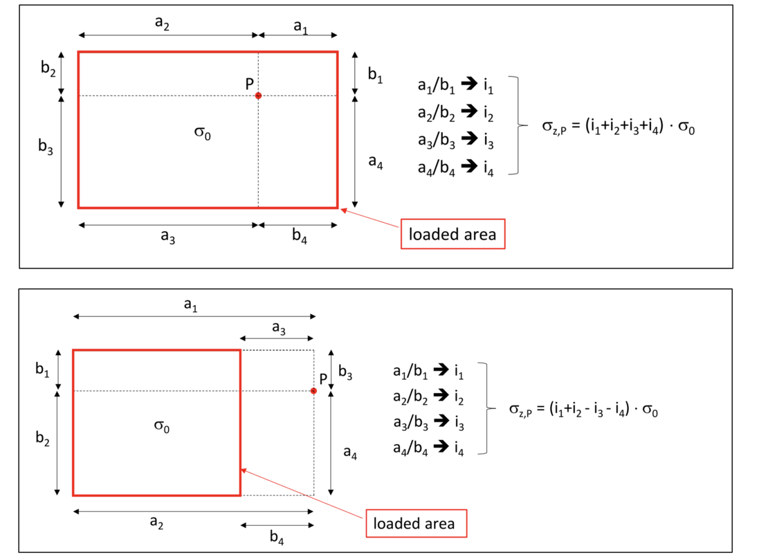
Further examples of the solution strategy in the course of determining stresses at different locations for loading surfaces with a wide variety of geometries can be found in the glossary entry "Calculation of settlements with stresses according to the Steinbrenner-table".
1.3 Stresses under a rigid foundation
The locations where the settlements of a flexible and a rigid foundation are the same are called "characteristic points", CP. The settlements of rigid foundations can therefore also be determined using the calculations for flexible foundations if the stresses σz,CP below the characteristic points are known.

In the case of a rectangle, the characteristic point CP is at 0.74 • a/2 or 0.74 • b/2, in the case of a circle at a distance of 0.845 • r from the center as shown below.
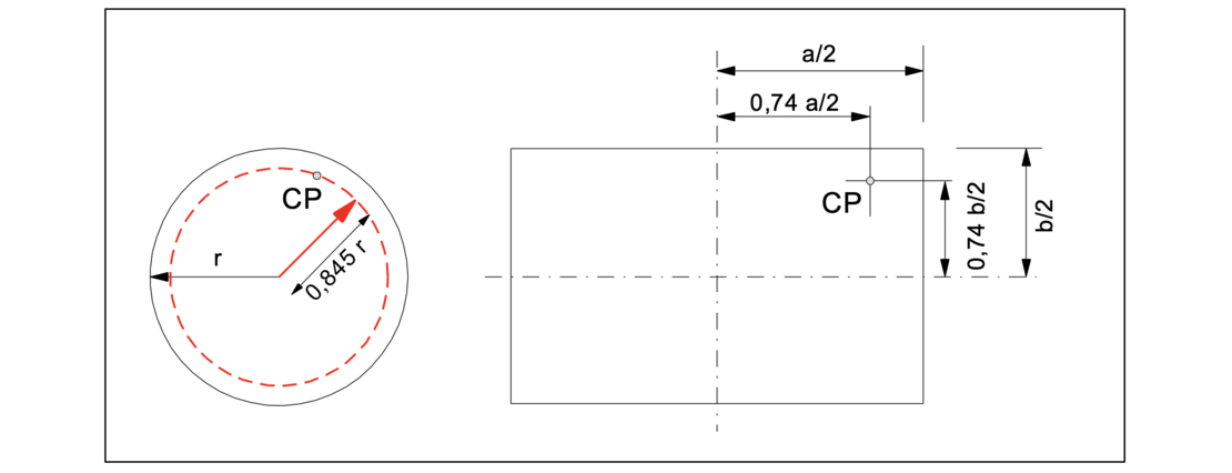
Influence factors “i” according to Kany are available for calculating the stresses below the characteristic point. A subdivision of the total load area into sub-rectangles is already considered in those influence factors.
2. Calculation of settlements
2.1 Calculation of settlements resulting from vertical stresses
The settlement s due to the loading of the soil can be calculated as the integral of the strains ε over the depth z using the following equation:

Therefore, to determine the settlements, it is necessary to know:
- the course of vertical stresses σz with depth. The settlement-generating base stress σ1 = σ0 - γ • h must be used, taking into consideration the stress reduction by the excavation unloading for the embedment depth of the foundations.
- the stress-dependent constrained moduli of the soil layers
- the value of the limiting depth
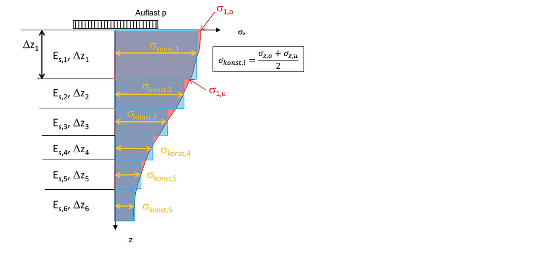
For an approximate calculation of the settlements, the course of vertical (settlement-generating) stresses is divided into sub- layers to be considered, so-called lamellas, with thicknesses Δzi. For a good approximation, the course of the stresses in these partial layers should be approximately linear. The loading of the surface results in a stress increase in each individual lamella. To calculate the settlement fractions, the mean constant stresses σkonst,i are determined for all i lamellas. The total settlement is equal to the sum of the partial settlements of all lamellas. An example with 6 lamellas is shown below.

2.2 Calculation of settlements with closed formulas
The method for calculating the settlements s due to the stress at the base of the foundation σ0 is based on values for the average constrained modulus Em and the equation

The term σ0⋅b⋅f stands for the integral of the stress course up to the limiting depth. DIN 4019 refers to tables for the determination of the settlement coefficient f according to Kany. This table is applicable for an unstratified soil with a mean constrained modulus. If this method is to be used to calculate the settlements in a stratified soil, settlement coefficients are determined for each individual layer; the settlement fractions of the individual layers result from the difference in the settlement coefficients:

2.3 Limiting depth
DIN 4019 limits the thickness of the compressible layer at a depth where the settlement-generating stresses σz become less than 20% of the overburden stresses σ0. This depth is designated by the limiting depth, tlimit.
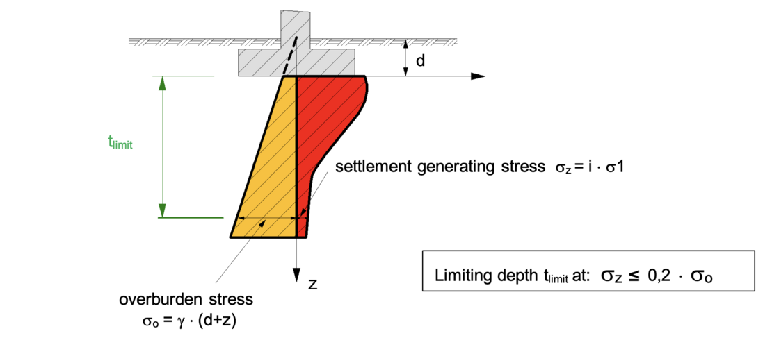
Beyond this limiting depth, settlement components are no longer taken into consideration unless, for example, there are highly settlement-sensitive soil layers below the limiting depth that still make a significant contribution to the total settlement.
3. Consolidation settlement
In the previous chapters the calculation of total final settlements was presented. However, cohesive soils react with delayed settlements which depend on the grain composition and the water content. The settlements in soil layers consist of three components:

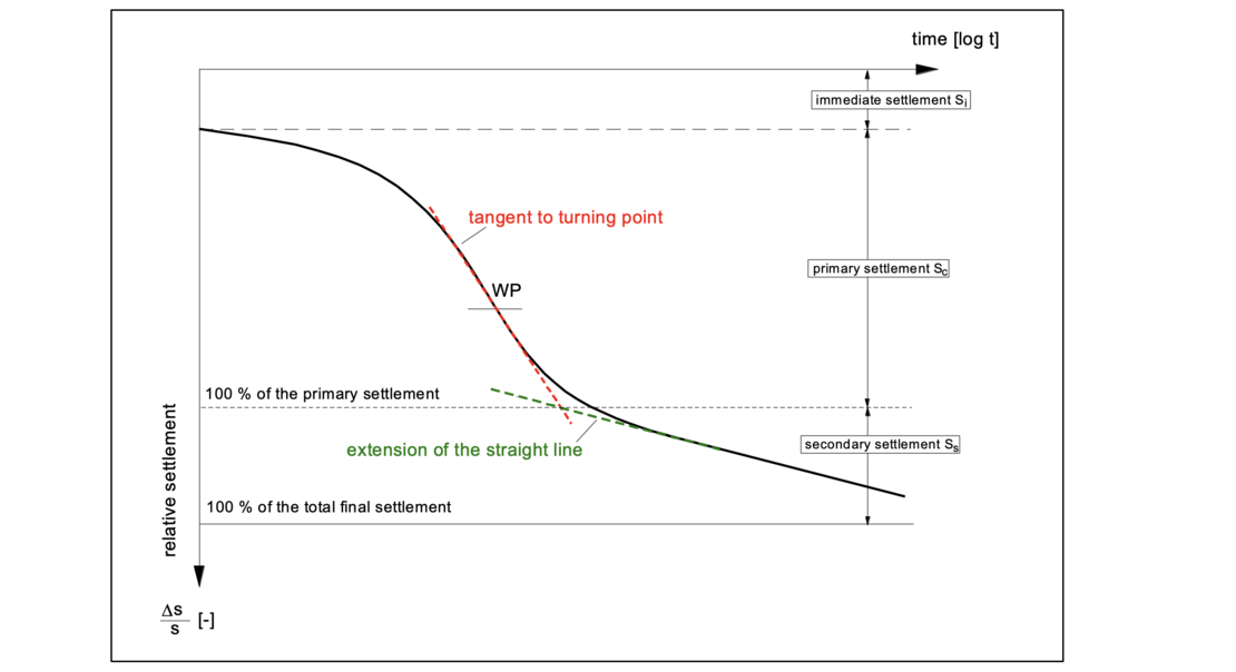
Si are settlements that occur immediately and do not involve any changes in the volume of the soil. The soil deflects laterally under the load. This is often referred to as elastic settlement.
Sc is called consolidation settlement. It is associated with a volume change in the soil. The water present in the cohesive soil is squeezed out and the soil adopts a higher density. Due to the very low water permeability of cohesive soils, no equilibrium in grain-to-grain pressure can be established immediately after loading, but in the process of water squeezing out, this equilibrium will be established as the water content decreases. With time, therefore, the excess pore water pressure created by the loading will be reduced. The settlements are thus established by the reduction of the excess pore water pressure. Sc is also referred to as primary settlement. In non-cohesive soils, the primary settlements occur at time t = 0 because of the high permeability.
Secondary settlements Ss are caused by creep processes in the soil, and are caused by long-lasting viscous flow phenomena of the grain structure. In the time-settlement diagram, the secondary settlements can be seen to grow steadily after the primary settlements. The time-settlement line therefore does not asymptotically approach a horizontal line.
Immediately after the immediate settlement Si (t = 0) the consolidation process starts, the consolidation settlements Sc grow. The transition from primary and secondary settlements is defined - in the logarithmic scale – by the intersection of the tangent to the turning point of the time-settlement line for the primary settlement and the extension of the straight line describing the secondary settlements as shown in the following figure.
According to Terzaghi (1923), the differential equation describing a one-dimensional consolidation process is:

This equation is a partial linear and homogeneous differential equation of 2nd order. The term cv is the so-called coefficient of consolidation. With the permeability of the soil kf, the dead weight of the water γw and the constrained modulus Es, it results in:

A Bernoulli product approach is used to solve this differential equation where φ(t) is a function dependent on time only and ψ(z) is a function dependent on depth only.

This splits the partial differential equation into two ordinary differential equations. For the solution an initial condition (isochrone at t = 0) and two homogeneous boundary conditions (drainage conditions) are needed. After some transformations two ordinary differential equations are obtained

which have the following solutions:

For the solution, the dewatering boundary conditions must be incorporated into these equations so that the constants C1 to C3 can be determined. With the resulting equations for the excess pore water pressure Δu as a function of time and depth z, isochrones can be calculated for various initial and boundary conditions. They are available as graphs in many standard textbooks.
3.1 Degree of consolidation
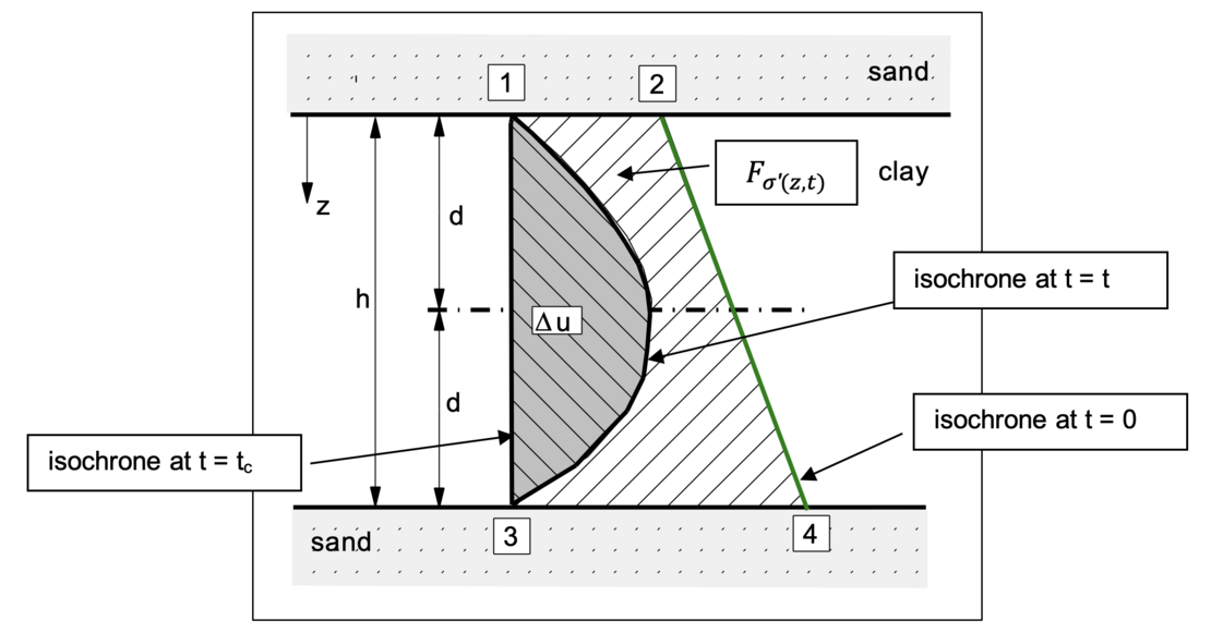
The primary settlement fractions of a cohesive soil s(t) result from the volume of water squeezed out. They strive towards a limit value s(t = ∞) which represents the total final settlement. Their ratio is called the degree of consolidation uK.

with

results in:

Illustratively, the degree of consolidation uK is the ratio of the hatched (white) area Fσ’(z,t) as the effective stress at time “t” to the total area 1234 as the effective stress at time t = ∞. As an example, a clay layer to be drained with a two-way drainage is shown here.
4. Example of the use of the computer program GGU-SETTLE
For the example shown of a 100 m long and 35 m wide embankment with a height of 5 m above the ground surface, the following video shows how the settlement analysis can be carried out using the computer program GGU-SETTLE program. For this example, it is assumed in a simplified way that the soil stratification shown does not change along the longitudinal axis of the embankment.
5. Example of the use of the computer program GGU-CONSOLIDATE
For the example shown of an 8 m thick clay layer loaded with an unlimited surface load of p = 25 kN/m², the time for a degree of consolidation of Uk = 85 % and the corresponding settlement of the ground surface are to be determined in accordance with the one-dimensional consolidation theory using the computer program GGU-CONSOLIDATE.
Notes on use
All texts, images and media listed here are subject to copyright and are the intellectual property of Civilserve GmbH. Use is only permitted with appropriate reference and a link to this source.