Bearing capacity
Table of content
1. Fundamentals
To ensure adequate bearing resistance the bearing capacity has to be verified for the limit state GEO-2. In this case the characteristic bearing capacity Rn,k has to be determined in accordance with DIN 4017.
As the load on a foundation increases, the normal stresses increase to the same extent. The settlements become larger. As the load increases even further, the maximum values of the base stresses shift towards the centre of the footing.
If the load is increased and exeeds the bearing capacity, the footing sinks into the ground without any further increase in load. Here a parable of a pile can be used, which is rammed into the ground unpointed. The soil below the footing cannot be compacted further and is displaced laterally. At this stage, a load-settlement curve has a vertical tangent. A tip of compacted soil forms under the footing. This tip is pressed in front of the footing and displaces further soil laterally, which bulges up at the ground surface. In the case of centrally loaded footings, a one-sided and two-sided bulging is possible. The one-sided bulging naturally results in a tilted position of the footing.
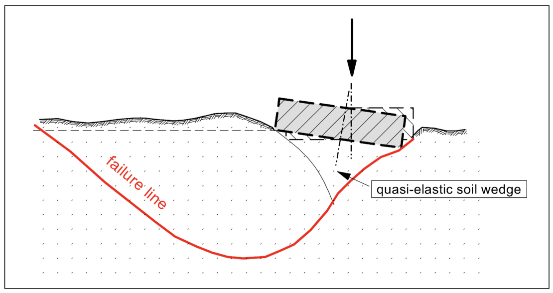
The magnitude of the bearing capacity depends among other aspects on
- the shear strength expressed by the angle of friction and the cohesion of the soil
- foundation depth
- foundation width
- eccentricity of the attacking actions
- horizontal actions
The influence of the above-mentioned dependencies is taken into account, among other things, with the aid of coefficients for calculating the characteristic bearing capacity Rn,k.
2. Bearing capacity
The characteristic value of the bearing capacity Rn,k is calculated using a three-part formula according to DIN 4017:
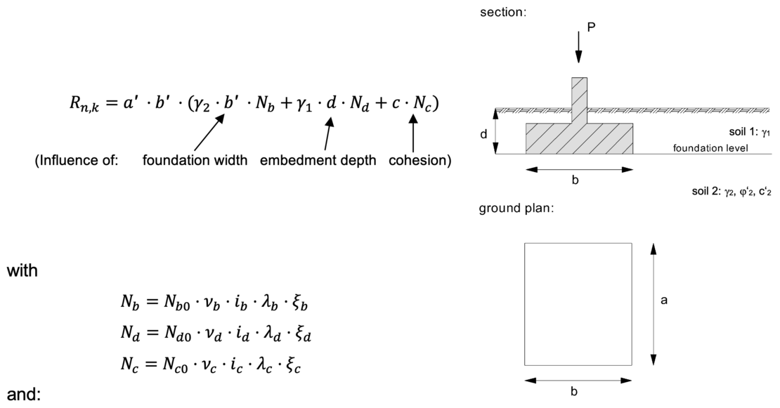
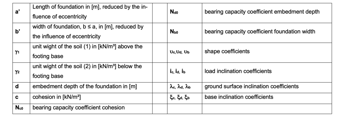
For detailed information on the calculation of the bearing capacity, please refer to DIN 4017.
3. Coefficients
The bearing capacity coefficient Nd0 is developed from an equilibrium consideration on the sliding body. Nb0 and Nc0 are obtained empirically with the aid of Nd0. They are given in DIN 4017 as a function of the friction angle:

In case of φ‘ = 0, Nd0 = 1 and Nc0 = 5.14. DIN 4017 contains graphs and tables for easy determination of the coefficients.
The original bearing capacity equation was established for strip foundations. By introducing so-called shape coefficients ν, it could be extended to rectangles, squares and circles. These shape coefficients depend on the dimensions a’ and b’ and also on the friction angle of the soil. The shape coefficients are specified in DIN 4017:

The load inclination angle δ (δ<φ) can be expressed with:

The characteristic value of the bearing capacity is to be determined taking into account the inclination of the resulting characteristic or representative load in the foundation base. The load inclination coefficients ib, ic and id can be taken from the following table in DIN 4017 as a function of the load inclination angle δ and its sign:

The exponent "m" is calculated as follows

The angle ω can be found between the orientation of the force T projected on the ground plan and the direction of a', see DIN 4017.
The ground surface inclination coefficients λ are valid under the condition that β < φ‘ and for foundations whose longitudinal axis is approximately parallel to the slope edge:
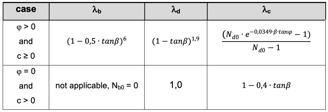
For β > φ‘, an investigation of the overall stability (slope failure) must be carried out according to DIN 4084.
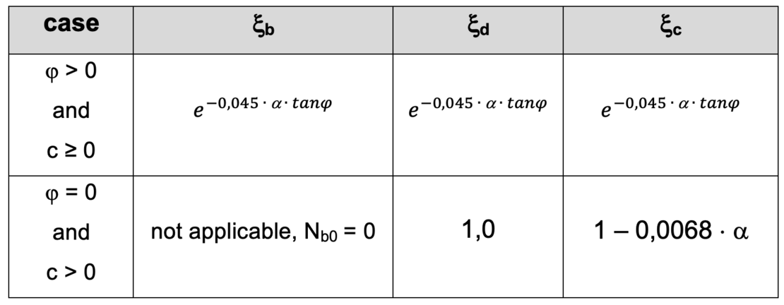
If the base of the considered foundation is inclined by the angle α ( α is positively inclined if the sliding body shifts in the direction of the horizontal component Nh), the influence of the bearing capacity can be taken into account via the base inclination coefficients:
To take into account a berm of width s located next to the foundation when calculating the bearing capacity Rn,k in conjunction with the above-mentioned slope coefficients, the equivalent embedment depth d' shall be used

According to DIN 4017, a comparative calculation shall be performed with β = 0 and d' = d, the lower value for the bearing capacity is decisive for the safety verification.
If the ground consists of soft or very soft, water-saturated, cohesive soil and a solid surface layer with a friction angle φ > 25°, whose thickness d1 is less than twice the foundation width b, the bearing capacity must also be determined according to the punching condition. The longer side of the foundation is designated by “a”. This resistance may be calculated as follows:
with
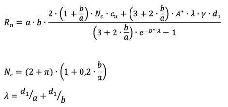
for rigid footings:

for flexible footings:

4. The safety verification
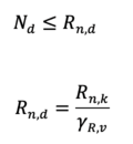
The verification of the bearing capacity is performed for the limit state GEO-2 according to DIN EN 1997-1 with the following equation. The design value of the bearing capacity Rn,d results from the characteristic bearing capacity Rn,k and the partial safety factor γR,v:
with
5. Example of the use of the computer program GGU-FOOTING
For the example shown below of a foundation with dimensions 4m x 2m and the given characteristic actions in the foundation base, the computer program GGU-FOOTING is used to carry out verifications for
- the bearing capacity (GEO-2),
- highly eccentric loads (EQU),
- limitation of misalignment (SLS) and
- sliding resistance (GEO-2)
for the design situation DS-P. The magnitudes of the characteristic actions are:
permanent: Pz,k = 1000 kN, Hy,k = 200 kN, Mx,k = 500 kN,
variable: My,k = 200 kN.
Notes on use
All texts, images and media listed here are subject to copyright and are the intellectual property of Civilserve GmbH. Use is only permitted with appropriate reference and a link to this source.