Soldier pile walls
Table of contents
1. Soldier pile walls
Soldier pile walls represent a development of timbered trenches and can be used as retaining walls even for large excavation pit depths in almost any soil type above the groundwater table. The following sketch shows the components of soldier pile walls.
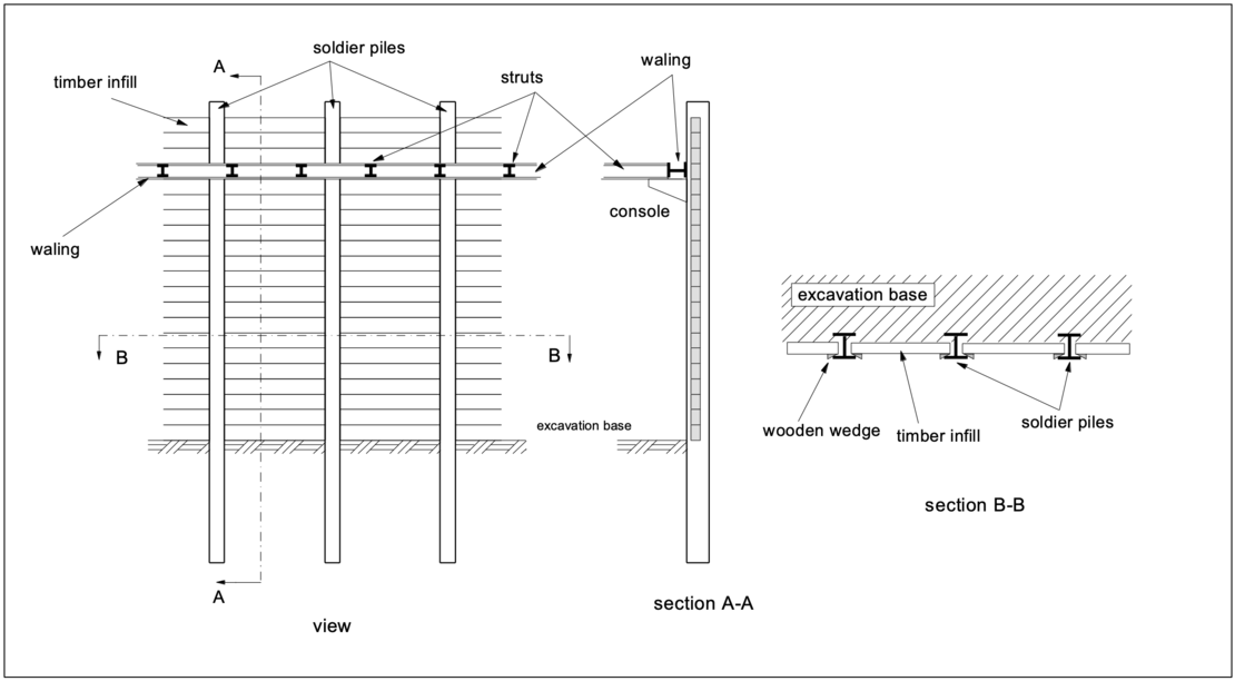
Structural elements of a soldier pile wall are, as shown in the picture:
- soldier piles (HE-A, HE-B, HE-M, U-shaped profiles)
- infill (usually timber) with wooden wedges
- steel waling and steel struts
- possibly grouted anchors (for systems anchored back into the ground)
Soldier pile walls are used as retaining walls for a temporary securing of excavation pit walls above the groundwater table.
Do you want to get started directly with the design of Soldier pile walls? Just one "mouse click" will take you to the license variants of the software solution: GGU-RETAIN.
2. Construction process
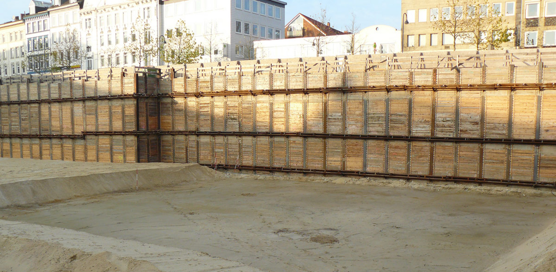
Vertical soldier piles - e.g. HE-A, HE-B, HE-M or composite U-sections - are driven into the ground either with vibratory or hammer drivers. Their distance is usually approx. 1 - 3 m from each other. In order to avoid strong vibrations and noise emissions or in the case of a soil that cannot be vibrated or rammed, the soldier piles can be inserted in pre-drilled holes. The borehole can be cased or suspension-supported. Composite profiles such as double U-profiles can also be inserted into the boreholes. After insertion, the remaining space is filled with sandy material, lean concrete or even lime mortar.
After insertion of the solder piles, the excavation of the pit can begin. According to DIN 4124, installation of the timber infill must begin at the latest when an excavation depth of 1.25 m has been reached. Unfavorable soil conditions may also reduce the possible excavation depth. Following the excavation, the timber infill is inserted between the flanges of the steel girders and pressed firmly and immovably against the soil behind them using wooden wedges. As an alternative to the use of wood, steel elements, shotcrete, prefabricated reinforced concrete elements, among others, can be used as infill. The individual parts of the infill must be long enough to rest on at least one fifth of the flange width of the beam on each side.
The installation of the further infill may lag behind the excavation by a maximum of 1 m in the case of stiff or semi-solid cohesive soils, and by a maximum of 0.5 m in the case of only temporarily stable, non-cohesive soils.
For the vertical capacity (transfer of vertical forces), the soldier piles must be embedded in the soil. The verification of the vertical capacity must be carried out for loads, the vertical earth pressure component, the vertical force components from anchors, etc..
If the soldier piles have been placed in boreholes, the next figure shows three possibilities for the transfer of vertical loads into the ground.
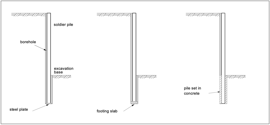
For small vertical forces, steel plates stapled to the foot of the soldier pile are sufficient for the load transfer and remain in the ground when the soldier pile is pulled in the process of deconstruction. If larger forces need to be transferred into the ground, a footing slab can be placed at the bottom of the borehole so that the soldier pile in combination with a steel plate at its foot distributes the load over a lager area. For very large vertical forces, the soldier pile can be embedded with concrete in the borehole. However, recovery of the soldier pile is then no longer possible.
3. Different types of soldier pile walls
A distinction of soldier pile walls is made between the so called "Berliner Verbau", "Hamburger Verbau" and "Essener Verbau". These names are mainly known in Germany and result among others from different soil conditions in different regions.
The “Berliner Verbau” was developed at the beginning of the 20th century during the construction of the Berlin subway. Since the predominant soils in the Berlin area, sand and gravel, are easy to drive the piles in, the soldier piles can be placed very accurately in their planned position in the ground. If no working space is required, the excavation pit wall can be used as formwork for e.g. a tunnel construction. This eliminates the need for a larger working space between the structure to be built and the retaining wall. For deconstruction the soldier piles can be pulled out again, the timber infill, however, remains in the ground.
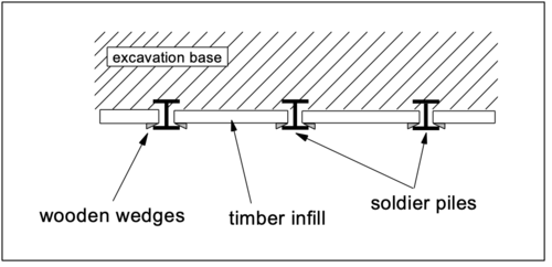
The “Essener Verbau” is similar to the “Berliner Verbau”, but instead of HE-A, HE-B or HE-M piles, two U-profiles are used as soldier piles side by side. For anchored retaining walls the grouted anchors can be arranged directly between these U-sections.
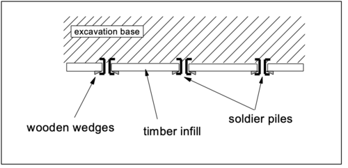
The “Hamburger Verbau” is also known as the soldier pile wall with curtain planks. The excavation pit side of the soldier pile flanges represents the excavation limit. This eliminates the need for time-consuming shaping of the soil for inserting the timber infill. The planks are placed in front of the steel girders and fixed with clamps. In the case of “Hamburger Verbau”, a working space is required between the soldier pile wall and the building to be constructed, which also allows the planks to be removed after completion of the construction work. This type of construction is now rarely used.
4. Profiles and infill
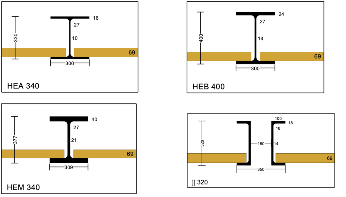
In general, HE-A, HE-B, HE-M and U-profiles are used for the soldier piles, depending on the structural requirements.
For the infill of soldier pile walls, wooden squared planks with dimensions according to the static requirement are usually used. It is also possible to use shotcrete, precast concrete elements or steel profiles.
5. Static systems
Static systems are used to calculate internal forces and state variables, which depend on the selected embedment depth and anchors or struts in one or more planes:
- unsupported wall, fully fixed earth support
- single / multiple supported wall with free earth support
- single / multiple supported wall, fully fixed earth support
- single / multiple supported wall, partially fixed earth support
The calculation of soldier pile walls can be carried out according to several procedures. The classical methods refer to the earth pressure theory and thus vary depending on the static system with regard to the magnitude and distribution of the earth pressure and the reaction forces in the soil. Basic systems are single or multiple supported beams that are freely supported or have a fixed earth support. A partially fixed earth support is also possible. More detailed information on the calculation methods, the approach to earth pressure, etc. is given in the EAB (Empfehlungen des Arbeitskreises “Baugruben”), among others. Computer aided methods also allow for the consideration of a bedding of the beam.
For a fully fixed earth support a rotation of the wall around a low-lying pivot point is necessary. The position of the pivot point is slightly above the base of the wall. Underneath, deformations occur that are directed towards the earth side and mobilize a reverse passive earth pressure there. For a simplified calculation, the BLUM equivalent force C is applied to the theoretical pivot point, which replaces the passive earth pressure below the pivot point and additionally corrects the simplified assumed passive earth pressure on the excavation side. Together with the resultant of the passive earth pressure this equivalent force C forms a pair of forces that represents the fixing of the soldier pile footing.
Do you want to get started directly with the design of Soldier pile walls? Just one "mouse click" will take you to the license variants of the software solution: GGU-RETAIN.
6. Necessary computational verifications
The calculation, design and construction of excavation pits are dealt with in detail in "„Empfehlungen des Arbeitskreises Baugruben“, EAB. For soldier pile walls, the following individual verifications are required for the limit states specified in the EAB, in DIN EN 1997-1 and in DIN 1054. The mentioned verifications can be performed using the computer program GGU-RETAIN:
Analysis of the bearing capacity of structural elements (limit state STR and GEO-2):
- Bearing capacity of soldier piles
- Bearing capacity of timber infill
- Bearing capacity of waling
- Bearing capacity of struts
- Bearing capacity of tension piles and ground anchors
Analysis approaches for soldier pile walls (GEO-2):
- Soil reactions and passive earth pressure for soldier pile walls
- Equilibrium of horizontal forces for soldier pile walls
- Analysis of the transfer of vertical forces into the subsurface
- Verification of stability at the lower failure plane (deep seated stability)
Analysis of general stability for a braced excavation (GEO-3)
The verification of the overall stability must be carried out. This analysis can be performed using the computer program GGU-STABILITY.
The serviceability limit state (SLS)
The serviceability limit state refers to the verification against large deformations of the retaining wall. Unfavorable deformations of the structure by actions loading the soldier pile must be prevented. Also the appearance, the unrestricted use of the structure, the adjacent structures, etc. may not be impaired. Limit values for deformations or deflections are determined on a project-specific basis and are not defined on a higher level.
As a rule, retaining walls belong to the geotechnical category GK 2. However, more complex conditions justify a classification in the geotechnical category GK 3. These include inner-city excavation pits with adjacent settlement-sensitive buildings, inclined grouted anchors that are to be used as permanent anchors and the presence of a confined groundwater table.
7. Example of the use of the computer program GGU-RETAIN (incl. video)
For the example shown below, a single supported soldier pile wall with a fully fixed earth support, the following video shows how the necessary verifications (design situation DS-T) can be performed using the computer program GGU-RETAIN:
Notes on use
All texts, images and media listed here are subject to copyright and are the intellectual property of Civilserve GmbH. Use is only permitted with appropriate reference and a link to this source.