Sheet pile walls
Table of contents
1. Sheet pile walls (Retaining walls)
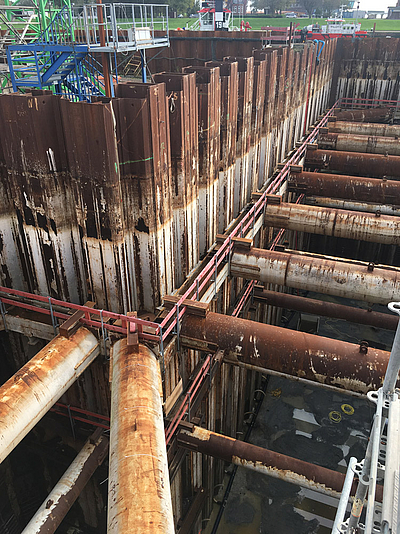
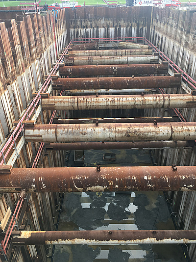
Sheet pile walls are required as retaining walls for the temporary securing of excavation pit walls. They are also used for permanent use, e.g. in harbor constructions as a landing place, as a bank wall, as an abutment of bridge superstructures or as a seal installed in a dam.
Due to the wide range of possible combinations of sheet pile profiles and as mixed profiles combined with various steel piles with the help of appropriate interlocks, the necessary moments of resistance can be achieved easily to meet the corresponding requirements. Large spans or large terrain jumps can thus be bridged.
Sheet piles walls are used in dry soils and in soils in groundwater. Due to the approximate watertightness of the sheet pile locks they are even used in flowing water, e.g. for the construction of the foundation of river piers of a bridge superstructure. Today, sheet piles are almost exclusively made of steel sections, generally U-shaped or Z-shaped profiles.
Do you want to get started directly with the design of retaining walls? Just one "mouse click" will take you to the license variants of the software solution: GGU-RETAIN.
2. Driving techniques
Three methods for driving sheet pile walls into the ground are known:
- hammer driving,
- vibratory driving,
- hydraulic jacking.
The choice of driving method depends, among other things, on the properties of the ground, the embedment depth, boundary conditions such as any neighboring buildings, the sheet pile profile to be installed and, of course, environmental protection requirements.
Driving with a fast impact sequence or vibrating liquefies non-cohesive soils so that the skin friction is reduced and the sheet pile can be driven into the soil by its own weight and the weight of the driving device. The presence of water in the soil supports the reduction of skin friction.
In cohesive soils, pile drivers with a slow impact sequence are advantageous. With each impact the excess pore water pressure builds up and increases the penetration resistance. So with some time between the impacts of the pile driver the excess pore water pressure decreases and thus the penetration resistance can be reduced.
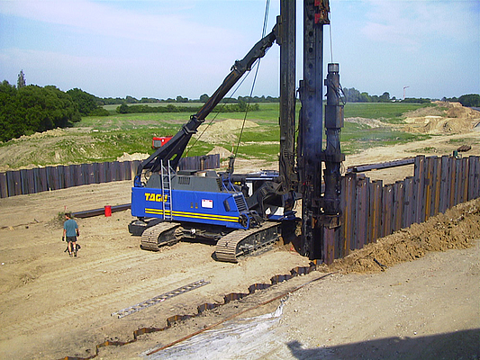
Slow impact free fall hammers, diesel hammers and quick impact hammers are used as pile drivers. The weights are lifted by cable pulls (free-fall hammers), by explosive combustion of injected diesel (diesel hammers) or by compressed air/steam (quick-impact hammers). In the case of hydraulically driven hammers, the piston can be additionally accelerated during the downward movement. This increases the energy acting on the sheet pile. The weight of the impact body / piston is roughly based on the weight of the driven material.
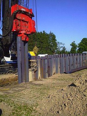
In vibratory pile drivers, the vibrations are generated by means of eccentric weights, moving in opposite directions producing counter-rotating imbalances. Horizontal components of the centrifugal forces are eliminated. Only vertical centrifugal forces are generated, which cause the pile to vibrate vertically. The driving of sheet piles with vibratory drivers is an economical method that combines lower driving times with lower emissions (noise, vibrations).
Hydraulic jacking of sheet piles produces less noise and fewer vibrations than hammer driving or vibratory driving. With this method, vibration-sensitive buildings can be protected and unacceptable noise can be avoided. Hydraulic jacking cannot be carried out in some soils, such as very hard cohesive soils. The skin friction and the peak resistance can be too high there.
3. Used materials
Today, sheet pile walls are almost exclusively made of steel profiles. These are used when approximately watertight retaining walls are required. Wooden and reinforced concrete sheet pile walls are practically meaningless. Instead, bored pile walls or diaphragm walls are usually constructed to guarantee the necessary moments of resistance in the case of large terrain jumps.
In addition to steel sheet pile walls, plastic sheet pile walls have also been produced for some time, which are used, among other things, as a bank protection or as a core seal in sealing walls. Plastic sheet pile walls provide a high resistance to chemical exposure.
4. Profiles
Generally U- and Z-shaped profiles are used. As the following examples show, these sheets can be combined in any way with soldier piles, box piles and tubular soldier piles to thus generate large moments of resistance.
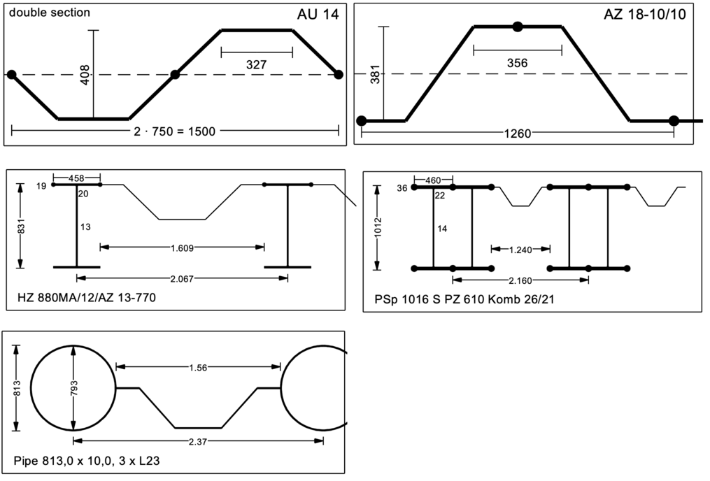
Different manufacturers offer sheet pile walls that combine U- and Z- shaped profiles, soldier piles and tubular pipe profiles.
5. Static systems
Static systems are used to calculate internal forces and state variables, which depend on the selected embedment depth and anchors or struts in one or more planes:
- unsupported wall, fully fixed earth support
- single / multiple supported wall with free earth support
- single / multiple supported wall, fully fixed earth support
- single / multiple supported wall, partly fixed earth support
The calculation of sheet pile walls can be carried out according to several procedures. The classical methods refer to the earth pressure theory and thus vary depending on the static system with regard to the magnitude and distribution of the earth pressure and the reaction forces in the soil. Basic systems are single or multiple supported beams that are freely supported or have a fixed earth support. A partly fixed earth support is also possible. More detailed information on the calculation methods, the approach to earth pressure, etc. is given in the EAB (Empfehlungen des Arbeitskreises “Baugruben”) and the EAU (Empfehlungen des Arbeitsausschusses “Ufereinfassungen”) , among others. Computer aided methods also allow for the consideration of a bedding of the beam.
For a fully fixed earth support a rotation of the wall around a low-lying pivot point is necessary. The position of the pivot point is slightly above the base of the wall. Underneath, deformations occur that are directed towards the earth side and mobilize a reverse passive earth pressure there. For a simplified calculation, the BLUM equivalent force C is applied to the theoretical pivot point, which replaces the passive earth pressure below the pivot point and additionally corrects the simplified assumed passive earth pressure on the excavation side. Together with the resultant of the passive earth pressure this equivalent force C forms a pair of forces that represents the fixing of the sheet pile footing.
Do you want to get started directly with the design of retaining walls? Just one "mouse click" will take you to the license variants of the software solution: GGU-RETAIN.
6. Necessary computational verifications
For retaining walls made of steel sheet piles, the following individual verifications are necessary for the limit states mentioned:
- Internal failure or excessive deformation of the structure or structural elements, including the sheet pile wall itself, piles, anchorage, struts, wailing etc., in which the strength of the structural materials is significant in providing resistance (STR).
- Failure or excessive deformation of the ground, in which the strength of soil or rock is significant in providing resistance (GEO-2), as for example:
- Analysis of the earth support, rotational failure of embedded walls (embedment depth)
- Analysis of the mobilized passive earth pressure
- Analysis of the vertical capacity
- Analysis of the deep seated stability
- Analysis of the heave of anchor soil (deadman anchors)
- Analysis of the pull-out-resistance of anchors
- Hydraulic Heave, caused by hydraulic gradients (HYD)
- Wall deformations and displacements (SLS)
- The safety of the overall stability must be investigated in all cases (GEO-3). The wall rotates about a pivot point and the whole system, including the wall, the anchorage and the soil fails as a rigid body. The necessary verification can be carried out e.g. with the computer program GGU-STABILITY.
7. Example of the use of the computer program GGU-RETAIN (incl. video)
The following video shows how the necessary verifications for the design situation DS-P for a sheet pile wall with a fully fixed earth support and with a single anchor can be performed using the computer program GGU-RETAIN:
Notes on use
All texts, images and media listed here are subject to copyright and are the intellectual property of Civilserve GmbH. Use is only permitted with appropriate reference and a link to this source.