GGU-RETAIN
 GGU-RETAIN
Analysis of retaining walls based on the Recommendations of the German Working Group for Excavations and for Waterfront Structures (EAB + EAU).

The analysis of the following retaining walls can be carried out:
- Sheet pile walls
- Combined sheet pile walls
- Soldier pile walls, also with tubular sections
- Cast-in-place walls (diaphragm walls, bored pile walls, bored soldier pile walls)
- Mixed-in-place walls
Capabilities:
- Analysis after BLUM or with the modulus of subgrade reaction method
- Analysis of soldier pile walls and bored soldier pile walls with the p-y- method
- Choice of analysis using either partial safety factors according to EC 7, DIN 1054:2005, ÖNORM EN 1997-1 or global safety factor (DIN 1054 old)
- System input using absolute heights
- Analysis using active earth pressure, at-rest earth pressure and increased active earth pressure
- Active earth pressure coefficients according to DIN 4085, after Culmann or user-defined values
- Redistribution of the active earth pressure definable
- Consideration of earthquake according to EC 8 or EAU 1990, additionally consideration of a horizontal load from a rigid structure or from dead weight of the wall
- Passive earth pressure coefficients according to DIN 4085:2011, Streck, Caquot/Kerisel, Culmann or user-defined values
- Soil properties can be selected from an expandable database of common soils
- For the p-y-method: option to choose between non cohesive, cohesive-soft and cohesive-firm soils
- For the modulus of subgrade reaction method: subgrade reaction modulus along the embedment depth with any course possible
- Berms on the active and the passive side
- Bounded and double-bounded surcharges on the active and passive side
- For the p-y-method: option to choose between static and cyclic surcharges
- Loads with limited plan dimensions according to “Spundwand-Handbuch”, fig. 4.20, or DIN 4085:2017-08
- Consideration of displacement and action boundary conditions, anchors, struts, etc.
- Consideration of pre-tension and pre-deformations
- Consideration of the hydraulic gradient on the active and the passive side
- Horizontal water pressure approach: classical or with flow conduits according to the potential theory. With it: consideration of hydraulic gradients on the active and the passive side
- Steel analysis according to EC 3
- Expandable database using standard profiles for soldier piles and sheet piles
- Consideration of thickness loss by rust
- Possibility to allocate a steel retaining wall different sections
- Possibility to consider inserted beams for soldier pile walls, bored soldier pile walls and diaphragm walls
- Reinforced concrete design and crack width verification according to EC 2 for circular and rectangular cross-sections
- Print out table for the reinforcement distribution
- Buckling analysis according to DIN EN 1993-1-1 using 2nd order theory
- Verification of hydraulic heave safety and buoyancy safety
- Verification for base heave safety, heave of anchor soil
- Verification of the deep-seated stability with optimization of anchor lengths
- Verification of the pull-out resistance
- Design of infill for soldier pile walls
- Wailing design
- Anchor steel design
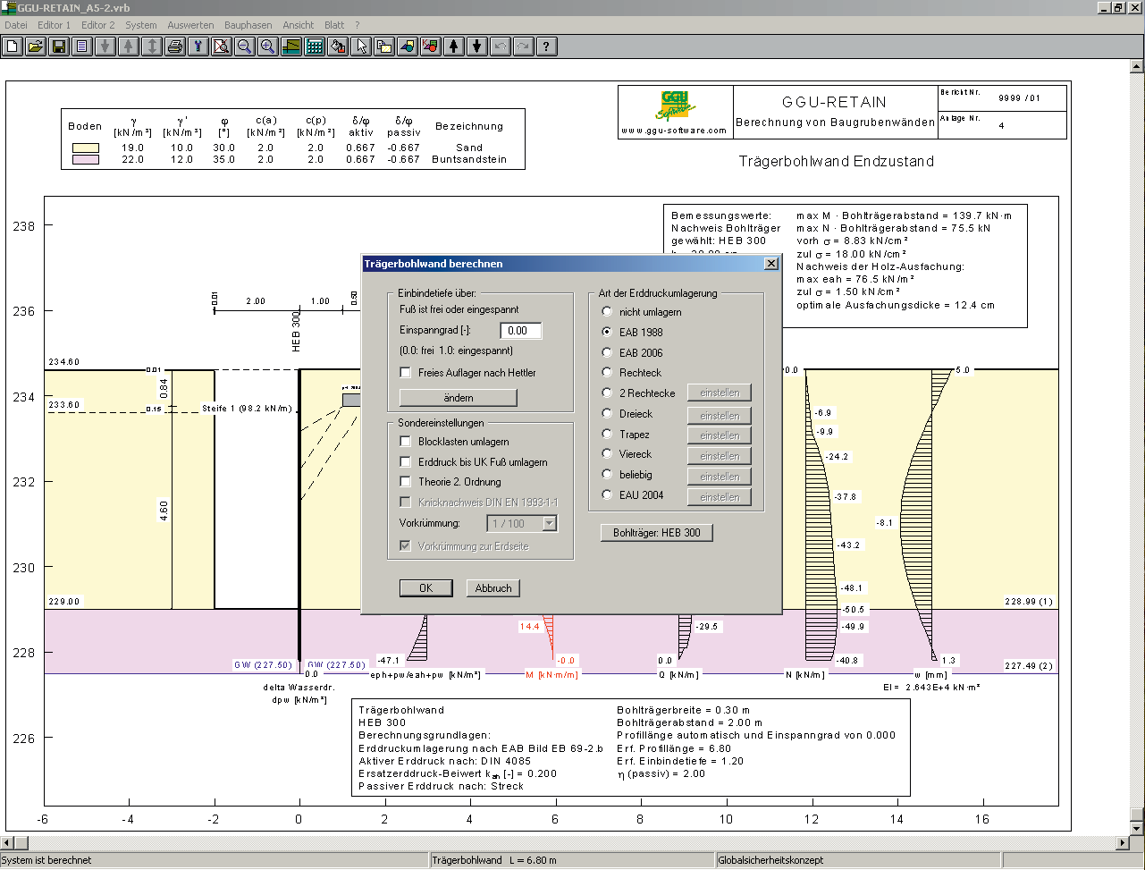
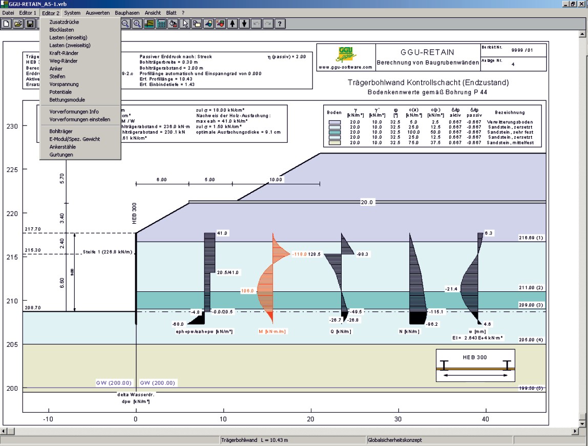
- Graphical visualization summarizing various stages of construction and retreating stages
- Choice of visualization of earth pressure, water pressure, moments, shear force, normal force and bending line
- Visualizing of the chosen retaining wall in a legend
- Interface to the computer program GGU-STABILITY for the verification of the global stability
- User-defined design of output sheet
- Print or copy screen sections, e.g. for transfer to a word processor
- Integrated Mini-CAD system for additional annotation of graphics
Current updates & changes
13.10 (14.07.2026)
- Bug: Wider berm on the passive side incorrectly leads to greater embedment depth and deformation
13.9 (10.07.2026)
- Bug: Reinforced concrete design incorrectly terminates with the message 'no reinforcement found' under nearly moment-free compressive loading
13.8 (19.06.2026)
- Feature: Optionally list the values of the load boundary conditions in the General Legend
- Bug: Font size setting "Boundary Conditions" does not affect the labeling of individual forces
- Bug: Reinforcement envelope of the diaphragm wall is identical for both sides of the wall instead of being side-separated when crack width verification is active
13.7 (17.06.2026)
- Bug: Pull-out resistance verification for multilayered anchoring incorrectly evaluated as not conducted in edge cases
- Bug: For berms, the additional earth pressure is applied over an excessively large depth range
13.6 (15.06.2026)
- Bug: Shaft friction for custom empirical values incorrectly doubled when verifying vertical forces
Show all entries
Online-Shop:
All prices incl. VAT
Information about our licenses
Simple and secure processing!
During the further order process you switch to the store system of our technology partners "WIBU Systems" and "cleverbridge". You can find out more about these companies under the following links.
 |  |
Additional information:
System preferences
GGU-Software runs on PCs with the following specifications:
- Pentium III or higher processor
- Microsoft Windows® (SAC), 11, Server 2016, 2019 and 2022 compatible
- 500 MB free hard disk space
- DVD-ROM drive or internet connection (for installation)
- USB Interface 2.0 or higher (for licence CmStick dongle)
- CmActLicences NOT on virtual maschines
1472,63 €
incl. VAT
365 days rent
- Free support
- Always current versions
- CmCloudContainer
- Supports virtual PCs
- Automatic license distribution
- Access via network/VPN
- Ends automatically
- Access for teams
981,75 €
incl. VAT
365 days subscription
- Free support
- Always current versions
- License binding to PC
- One program user
- Automatic renewal
- Annually cancelable
264,00 €
incl. VAT
10h PayPerUse
- All GGU applications included
- Free support
- Always current versions
- License binding to PC, CmCloudContainer or Dongle (CmStick with serial numbers starting with 3-344xxxx)
- Access via network/VPN
- Usage time by the minute
- All programs included
- Ends automatically
- Ideal for home office and license usage spikes
Webinars & Videos

Webinar
Construction Phases and Dismantling of Retaining Walls with GGU-RETAIN (44min)
This webinar will demonstrate the GGU-RETAIN program’s ability not only to design a retaining wall for a single – and final – depth of an excavation pit, but also to have a close look at state variables like moments, shear forces, displacements etc., which vary with different phases of the excavation. Additionally our expert Prof. Uwe Glabisch will lead you through the menu of the program GGU-RETAIN to outline its competence to compute the state of a dismantling, meaning here to cut a row of anchors and to…

Webinar
Retaining wall analysis with GGU-RETAIN (33min)
Using examples, Dr. Peter Grubert shows how calculate ond optimize retainig walls with GGU-RETAIN